HARDWARE REFERENCE RÉFÉRENCE MATÉRIELLE Gateway Computer Ordinateur Gateway
Contents Chapter 1: About This Reference . . . . . . . . . . . . . . . . . . . . . . . . . . . . . . . . . . . . . . . . . . . . . .1 About this guide . . . . . . . . . . . . . . . . . . . . . . . . . . . . . . . . . . . . . . . . . . . . . . . . . . . . . . . . Accessing the User Guide . . . . . . . . . . . . . . . . . . . . . . . . . . . . . . . . . . . . . . . . . . . . . . . . Gateway contact information . . . . . . . . . . . . . . . . . . . . . . . . . . . . . . . . . . . . . . . . . . . .
Contents ii www.gateway.
CHAPTER 1 About This Reference • About this guide • Accessing the User Guide • Gateway contact information • Microsoft Certificate of Authenticity 1
Chapter 1: About This Reference www.gateway.com About this guide This guide includes information and maintenance instructions that are specific to your model of Gateway computer. For all other computer information, see your online User Guide. Accessing the User Guide In addition to this guide, the User Guide has been included on your hard drive.
www.gateway.com Gateway contact information Gateway contact information The label on the side of your computer case contains information that identifies your computer model and serial number. Gateway Customer Care will need this information if you call for assistance. Onlin Tech e supp Supp Tech Supp ort: ort Phon ort e: Hou rs: (U.S. (Can) ada) 900439 4 Online support: Tech Support Phone: (U.S.
Chapter 1: About This Reference 4 www.gateway.
CHAPTER 2 Hardware Basics • Front • Back 5
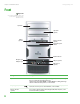
Chapter 2: Hardware Basics www.gateway.com Front Important Your computer hardware options and port locations may vary from the illustration below.
www.gateway.com Component Front Icon Description Power button and power indicator Press this button to turn the power on or off. You can also configure the power button to operate in Standby/Resume mode or Hibernate mode. The power indicator lights when the computer is turned on. Hard drive indicator Lights when the hard drive is in use. IEEE 1394 ports (optional) Plug IEEE 1394 (also known as Firewire® or i.Link®) devices (such as a digital camcorder) into these 6-pin IEEE 1394 ports.
Chapter 2: Hardware Basics www.gateway.com Back Important Your computer hardware options and port locations may vary from the illustration below. Power connector Voltage switch Case cover thumbscrew Audio in/side speaker jack Headphone/front speaker jack Microphone jack Center/subwoofer jack (optional) S/PDIF jack (optional) Rear speaker jack (optional) Ethernet (network) jack USB ports IEEE 1394/FireWire™/ i.
www.gateway.com Component Back Icon Description IEEE 1394 ports Plug IEEE 1394 (also known as Firewire® or i.Link®) devices (such as a digital camcorder) into these 6-pin IEEE 1394 ports. For more information, see the User Guide.. Parallel port Plug a parallel device (such as a printer) into this port. For more information, see the User Guide.. S-Video (TV) out jack (optional) Plug a standard S-Video device (such as a television) into this optional jack.
Chapter 2: Hardware Basics 10 www.gateway.
CHAPTER 3 Maintenance Basics • Preventing static electricity discharge • Opening the case • Closing the case • Installing memory • Replacing the system battery • Adding or replacing a CD or DVD drive • Replacing the memory card reader • Adding or replacing a hard drive • Replacing the front fan • Replacing the rear fan • Replacing the power supply • Replacing the heat sink and processor • Replacing the I/O board • Adding or replacing an expansion card • Replacing the system board 11
CHAPTER 3: Maintenance Basics www.gateway.com Preventing static electricity discharge Warning To avoid exposure to dangerous electrical voltages and moving parts, turn off your computer and unplug the power cord and modem and network cables before opening the case. The components inside your computer are extremely sensitive to static electricity, also known as electrostatic discharge (ESD).
www.gateway.com Opening the case 4 Remove the two thumbscrews on the side panel cover. Thumbscrews 5 Swing the side panel away from the back of your computer, then pull the panel off. Removing the front bezel To remove the front bezel: 1 Press the three bezel retention tabs, then swing the right side of the front bezel away from the computer and remove it.
CHAPTER 3: Maintenance Basics www.gateway.com Closing the case Replacing the front bezel To replace the front bezel: 1 Engage the tabs on the left side of the bezel with the slots in the left side of the computer. 2 Swing the right side of the bezel in to engage the tabs on the right side of the bezel with the slots on the right side of the computer. 3 Press the right side of the bezel firmly until it snaps into place.
www.gateway.com Installing memory Installing memory When you upgrade the computer memory, make sure that you install the correct type of memory module for your computer. Your computer uses DIMM memory. To install or replace DIMM memory: 1 Remove the side panel by following the instructions in “Removing the side panel” on page 12. 2 For more stability, place your computer on its side. To avoid scratching the case, place it on a towel or other non-abrasive surface.
CHAPTER 3: Maintenance Basics www.gateway.com 9 Turn on your computer. Windows starts and the Windows desktop appears. 10 Click Start, Control Panel, then click Performance and Maintenance (if in Category view). Click/Double-click System. The amount of memory in your computer is shown at the bottom of the System Properties dialog box in the General tab. Replacing the system battery Warning Danger of explosion if battery is incorrectly replaced.
www.gateway.com Adding or replacing a CD or DVD drive 10 Replace the side panel by following the instructions in “Replacing the side panel” on page 14. 11 Reconnect all external cables and the power cord. 12 Turn on your computer. 13 Open the BIOS Setup utility. 14 In the BIOS Setup utility, restore any settings that you wrote down in Step 3. 15 Save all your settings and exit the BIOS Setup utility.
CHAPTER 3: Maintenance Basics www.gateway.com 4 Remove the two drive retention screws, then slide the drive forward and out of the drive bay. Drive retention screws 5 Note any jumper settings on the old drive and set the jumper on the new drive to be the same. 6 Slide the new drive into the drive bay, line up the screw holes on the drive bay with the screw holes on the drive, then replace the two drive retention screws. Drive retention screws 7 Reconnect the drive cables using your notes from Step 3.
www.gateway.com Adding or replacing a hard drive 3 Remove the screws holding the card reader in the drive bay. Screws 4 Disconnect the card reader’s data cable from the system board. 5 Slide the card reader out of the case. Screws 6 Slide the new card reader into the bay from the front of the case. Important The color and shape of your replacement component's front cover may vary from your original component. 7 Connect the new card reader’s data cable to the system board.
CHAPTER 3: Maintenance Basics www.gateway.com 3 Disconnect the drive cables, noting their locations and orientation. (You will reconnect the cables after you install the new drive.) 4 Remove the front fan assembly by pulling it away from the system board. 5 Disconnect the fan cable from the system board.
www.gateway.com Adding or replacing a hard drive 6 Remove the hard drive bay screw. Hard drive bay screw 7 Remove the hard drive bay from your computer. You may need to work the bay out of your computer by rocking the bay back and forth. If you are adding a new drive, go to Step 10. 8 Remove the four screws that secure the hard drive to the hard drive bay, then remove the hard drive from the bay.
CHAPTER 3: Maintenance Basics www.gateway.com 9 Note any jumper settings on the old drive and set the jumper on the new drive to be the same. Jumper 10 Slide the new drive into the drive bay, then secure the drive to the bay using the four screws you removed previously. 11 Slide the drive bay back into your computer, making sure that the tabs on the bottom of the bay align with and slide into the slots on the bottom of your computer.
www.gateway.com Replacing the front fan Replacing the front fan Tips & Tricks You need a Phillips screwdriver to replace the front fan. To replace the front fan: 1 Remove the side panel by following the instructions in “Removing the side panel” on page 12. 2 Remove the front fan by pulling it away from the system board. 3 Disconnect the fan cable from the system board. 4 Connect the new fan cable to the system board, then insert the new fan into place.
CHAPTER 3: Maintenance Basics www.gateway.com Replacing the rear fan Tips & Tricks You need a Phillips screwdriver to replace the rear fan. To replace the rear fan: 1 Remove the side panel by following the instructions in “Removing the side panel” on page 12. 2 Disconnect the fan from the system board. 3 Remove the four screws that secure the fan to the back of the case, then remove the fan.
www.gateway.com Replacing the power supply Replacing the power supply Tips & Tricks You need a Phillips screwdriver to replace the power supply. To replace the power supply: 1 Remove the side panel by following the instructions in “Removing the side panel” on page 12. 2 Disconnect the power supply cables from all components (such as hard drives, CD or DVD drives, and the system board), noting their locations and orientation. (You will reconnect the cables after you install the new power supply.
CHAPTER 3: Maintenance Basics www.gateway.com Replacing the heat sink and processor Tips & Tricks You need a Phillips screwdriver to replace the heat sink. To replace the heat sink and processor: 1 Remove the side panel by following the instructions in “Removing the side panel” on page 12. 2 For more stability, place your computer on its side. To avoid scratching the case, place it on a towel or other non-abrasive surface. 3 Remove the fan by pulling it away from the system board.
www.gateway.com Replacing the heat sink and processor 5 Loosen the four screws that secure the heat sink to the system board, then remove the heat sink. Screws Screws 6 Release the processor by pushing down on the lever and then lifting it completely up. 7 Remove the processor from the system board.
CHAPTER 3: Maintenance Basics www.gateway.com Replacing the I/O board Important The color and shape of your replacement component's front cover may vary from your original component. To replace the front I/O panel: 1 Remove the side panel by following the instructions in “Removing the side panel” on page 12. 2 Remove the bezel by following the instructions in “Removing the front bezel” on page 13. 3 Disconnect the cable from the I/O panel.
www.gateway.com Adding or replacing an expansion card Adding or replacing an expansion card To add or replace an expansion card: 1 Remove the side panel by following the instructions in “Removing the side panel” on page 12. 2 If you are adding a new expansion card, go to the next step. If you are replacing an expansion card, go to Step 5. 3 Disconnect any cables that are attached to the card, noting their locations and orientation. (You may need to reconnect the cables after you install the new card.
CHAPTER 3: Maintenance Basics www.gateway.com Replacing the system board To replace the system board: 1 Remove the side panel by following the instructions in “Removing the side panel” on page 12. 2 Disconnect any expansion card cables from the card and from the system board, noting their locations and orientation. (You will reconnect the cables after you reinstall the cards.) 3 Open the card retention lever. Card retention lever 4 Remove any expansion cards.
www.gateway.com Replacing the system board 5 Remove the fan by pulling it away from the system board. 6 Disconnect the fan cable from the system board. 7 Find the memory module banks on your system board. 8 Gently pull the plastic tabs away from the sides of the memory modules, then remove them. 9 Disconnect the power and data cables from the system board, noting their locations and orientation. (You will reconnect the cables after you install the new board.
CHAPTER 3: Maintenance Basics www.gateway.com 10 Remove the three screws that secure the power supply to your computer. Screws 11 Slide the power supply away from the back of your computer, then pull it down and remove it. 12 Remove the seven system board screws. Screws Screws 13 Lift the system board up and out of the case. 14 Align the new system board on the screw holes in the case, then secure it into the case with the screws.
www.gateway.com Replacing the system board 16 Loosen the four screws that secure the heat sink to the system board, then remove the heat sink. Screws Screws 17 Release the processor from the old system board by pushing down on the lever and then lifting it completely up. 18 Remove the processor from the old system board.
CHAPTER 3: Maintenance Basics www.gateway.com 25 Reinstall any expansion cards you removed. 26 Replace the side panel by following the instructions in “Replacing the side panel” on page 14. © 2006 Gateway, Inc. All rights reserved. Gateway and eMachines are trademarks or registered trademarks of Gateway, Inc. in the United States and other countries. All other brands and product names are trademarks or registered trademarks of their respective companies.
Index Ethernet 8 external audio 9 external speakers 9 Firewire 7, 9 front speaker 9 headphone 9 i.
Index K keyboard PS/2 port 9 USB port 6, 9 L label Microsoft Certificate of Authenticity 3 product 3 line in jack 9 line out jack 9 M memory adding 15 installing 15 replacing 15 memory card reader locating 6 replacing 18 microphone jack 7, 9 Microsoft Certificate of Authenticity 3 modem jack 9 monitor port 9 mouse PS/2 port 9 USB port 6, 9 N network jack 8 O opening computer case 12 front bezel 13 optical drive locating 6 P parallel port 9 ports See connections power button 7 connector 8 Hibernate mod
Sommaire Chapitre 1 : À propos de cette référence . . . . . . . . . . . . . . . . . . . . . . . . . . . . . . . . . . . . . .1 À propos de ce guide . . . . . . . . . . . . . . . . . . . . . . . . . . . . . . . . . . . . . . . . . . . . . . . . . . . Accès au Manuel de l'utilisateur . . . . . . . . . . . . . . . . . . . . . . . . . . . . . . . . . . . . . . . . . Coordonnées de Gateway . . . . . . . . . . . . . . . . . . . . . . . . . . . . . . . . . . . . . . . . . . . . . . .
Sommaire ii www.gateway.
CHAPITRE 1 À propos de cette référence • À propos de ce guide • Accès au Manuel de l'utilisateur • Coordonnées de Gateway • Certificat d'authenticité Microsoft.
Chapitre 1 : À propos de cette référence www.gateway.com À propos de ce guide Ce guide contient des informations et des instructions de maintenance qui sont spécifiques à votre modèle d'ordinateur Gateway. Pour toutes les autres informations d'ordinateur, veuillez consulter votre Manuel de l'utilisateur en ligne. Accès au Manuel de l'utilisateur En plus de ce guide, le Manuel de l'utilisateur a été inclus sur votre disque dur.
www.gateway.com Coordonnées de Gateway Coordonnées de Gateway L'étiquette se trouvant sur le côté du boîtier de votre ordinateur comporte des informations qui permettent d'identifier le modèle et le numéro de série de votre ordinateur. Le service clientèle Gateway aura besoin de cette information lorsque vous appellerez pour obtenir de l'aide. Onlin Tech e supp Supp Tech Supp ort: ort Phon ort e: Hou rs: (U.S. (Can) ada) 900439 4 Online support: Tech Support Phone: (U.S.
Chapitre 1 : À propos de cette référence 4 www.gateway.
CHAPITRE 2 Généralités relatives au matériel • Avant • Arrière 5
Chapitre 2 : Généralités relatives au matériel www.gateway.com Avant Important Les options matérielles et emplacements des ports de votre ordinateur peuvent être différents de l'illustration ci-dessous.
www.gateway.com Composant Avant Icône Description Lecteur de carte mémoire (en option) Insérez la carte mémoire d'un appareil photo numérique, d'un lecteur MP3, d'un PDA ou d'un téléphone portable ou d'autres périphériques dans le lecteur de carte mémoire. Interrupteur d'alimentation et voyant d'alimentation Appuyez sur cet interrupteur pour mettre l'appareil sous tension ou hors tension.
Chapitre 2 : Généralités relatives au matériel www.gateway.com Arrière Important Les options matérielles et emplacements des ports de votre ordinateur peuvent être différents de l'illustration ci-dessous.
www.gateway.com Composant Arrière Icône Description Ports IEEE 1394 Branchez un appareil IEEE 1394 (aussi connu sous le nom de Firewire® ou de i.Link®) (tel qu'un caméscope numérique) dans l'un des ports IEEE 1394 à 6 broches. Pour plus d'informations, consultez le Manuel de l'utilisateur. Port parallèle Branchez un périphérique parallèle (tel qu'une imprimante) dans ce port. Pour plus d'informations, consultez le Manuel de l'utilisateur.
Chapitre 2 : Généralités relatives au matériel Composant 10 Icône www.gateway.com Description Port de clavier PS/2 Branchez un clavier PS/2 (Personal System/2®) dans ce port. Port de souris PS/2 Branchez une souris PS/2 dans ce port.
CHAPITRE 3 Généralités relatives à la maintenance • Prévention de décharge d'électricité statique • Ouverture du boîtier • Fermeture du boîtier • Installation de la mémoire • Remplacement de la batterie système • Ajout ou remplacement d'un lecteur de CD ou de DVD • Remplacement du lecteur de carte mémoire • Ajout ou remplacement d'un disque dur • Remplacement du ventilateur avant • Remplacement du ventilateur arrière • Remplacement du bloc d'alimentation • Remplacement du dissipateur thermique et du process
Chapitre 3 : Généralités relatives à la maintenance www.gateway.com Prévention de décharge d'électricité statique Avertissement Pour éviter l'exposition aux pièces mobiles et aux tensions électriques dangereuses, éteignez votre ordinateur et débranchez le cordon d'alimentation, le câble de modem et les câbles réseau avant d'ouvrir le boîtier. Mise en garde Les décharges électrostatiques peuvent endommager définitivement les composants de votre ordinateur qui y sont sensibles.
www.gateway.com Ouverture du boîtier 4 Enlevez les deux vis à oreilles du couvercle du panneau latéral. Vis à oreilles 5 Dégagez le panneau latéral en l'écartant de l'arrière de l'ordinateur, puis retirez-le. Démontage du cadre avant Pour démonter le cadre avant, procédez comme suit : 1 Appuyez sur les trois onglets de maintien du cadre, puis faites pivoter le côté droit du cadre en l'écartant de l'ordinateur et retirez-le.
Chapitre 3 : Généralités relatives à la maintenance www.gateway.com Fermeture du boîtier Remontage du cadre avant Pour remonter le cadre avant, procédez comme suit : 1 Insérez les onglets sur le côté gauche du cadre dans les logements sur le côté gauche de l'ordinateur. 2 Faites pivoter le côté droit du cadre pour engager les onglets sur le côté droit du cadre dans les logements sur le côté droit de l'ordinateur. 3 Appuyez fermement sur le côté droit du cadre jusqu'à ce qu'il se mette en place.
www.gateway.com Installation de la mémoire Installation de la mémoire Lorsque vous mettez à niveau la mémoire de l'ordinateur, veillez à installer le type de module de mémoire correct pour l'ordinateur. Votre ordinateur utilise des barrettes de mémoire DIMM. Pour installer ou remplacer des barrettes de mémoire DIMM, procédez comme suit : 1 Démontez le panneau latéral en suivant les instructions de la section « Démontage du panneau latéral » à la page 12.
Chapitre 3 : Généralités relatives à la maintenance www.gateway.com 6 Remontez le panneau latéral en suivant les instructions de la section « Remontage du panneau latéral » à la page 14. 7 Replacez l'ordinateur en position verticale. 8 Reconnectez les câbles et le cordon d'alimentation. 9 Allumez votre ordinateur. Windows démarre et le bureau de Windows s'affiche. 10 Cliquez sur Démarrer, Panneau de configuration, puis sur Performances et (si vous êtes en affichage par catégories).
www.gateway.com Ajout ou remplacement d'un lecteur de CD ou de DVD Batterie Onglet de dégagement 9 Assurez-vous que le pôle positif (+) de la nouvelle batterie est orienté vers le haut, puis enfoncez la batterie dans le support jusqu'à ce qu'elle s'enclenche en position. 10 Remontez le panneau latéral en suivant les instructions de la section « Remontage du panneau latéral » à la page 14. 11 Reconnectez tous les câbles externes et le cordon d'alimentation. 12 Allumez votre ordinateur.
Chapitre 3 : Généralités relatives à la maintenance Important La couleur et la forme du panneau avant du composant de remplacement peuvent être différentes de celles du composant d'origine. www.gateway.com 3 Si vous remplacez un lecteur existant, débranchez les câbles du lecteur en prenant note de leur emplacement et de leur orientation. Vous rebrancherez les câbles lorsque le nouveau composant aura été installé. (Lecteur de CD/DVD affiché.) Si vous installez un nouveau lecteur, passez à l'étape 6.
www.gateway.com Remplacement du lecteur de carte mémoire 8 Remontez le cadre avant en suivant les instructions de la section « Remontage du cadre avant » à la page 14. 9 Remontez le panneau latéral en suivant les instructions de la section « Remontage du panneau latéral » à la page 14. Remplacement du lecteur de carte mémoire Conseils et astuces Munissez-vous d'un tournevis cruciforme pour remplacer le lecteur de carte mémoire.
Chapitre 3 : Généralités relatives à la maintenance www.gateway.com 9 Réinstallez le cadre en suivant les instructions de la section « Remontage du cadre avant » à la page 14. 10 Réinstallez le panneau latéral du boîtier de l'ordinateur en suivant les instructions de la section « Remontage du panneau latéral » à la page 14.
www.gateway.com Ajout ou remplacement d'un disque dur 5 Débranchez le câble du ventilateur de la carte système. 6 Retirez la vis de la baie du disque dur. Vis de la baie du disque dur 7 Retirez la baie du disque dur de votre ordinateur. Vous devrez probablement balancer la baie vers l'avant et vers l'arrière pour la sortir de l'ordinateur. Si vous ajoutez un lecteur, passez à l'étape 10.
Chapitre 3 : Généralités relatives à la maintenance www.gateway.com 8 Retirez les quatre vis fixant le disque dur sur la baie de disque dur, puis retirez le disque dur de la baie. Vis Vis 9 Prenez note des paramètres du cavalier de l'ancien lecteur et configurez le cavalier du nouveau lecteur de la même manière. Cavalier 10 Glissez le nouveau disque dur dans la baie, puis fixez-le à la baie à l'aide des quatre vis précédemment enlevées.
www.gateway.com Remplacement du ventilateur avant 13 Rebranchez les câbles du lecteur en utilisant les notes que vous avez prises à l'étape 3. 14 Remontez le panneau latéral en suivant les instructions de la section « Remontage du panneau latéral » à la page 14. 15 Reconnectez tous les câbles externes et le cordon d'alimentation. 16 Allumez votre ordinateur.
Chapitre 3 : Généralités relatives à la maintenance www.gateway.com 4 Branchez le câble du nouveau ventilateur sur la carte système, puis insérez le nouveau ventilateur. 5 Remontez le panneau latéral en suivant les instructions de la section « Remontage du panneau latéral » à la page 14. Remplacement du ventilateur arrière Conseils et astuces Munissez-vous d'un tournevis cruciforme pour remplacer le ventilateur arrière.
www.gateway.com Remplacement du bloc d'alimentation 7 Reconnectez tous les câbles externes et le cordon d'alimentation. 8 Allumez votre ordinateur. Remplacement du bloc d'alimentation Conseils et astuces Munissez-vous d'un tournevis cruciforme pour remplacer le bloc d'alimentation. Pour remplacer le bloc d'alimentation, procédez comme suit : 1 Démontez le panneau latéral en suivant les instructions de la section « Démontage du panneau latéral » à la page 12.
Chapitre 3 : Généralités relatives à la maintenance www.gateway.com Remplacement du dissipateur thermique et du processeur Conseils et astuces Munissez-vous d'un tournevis cruciforme pour remplacer le dissipateur thermique. Pour remplacer le dissipateur thermique et le processeur : 1 Démontez le panneau latéral en suivant les instructions de la section « Démontage du panneau latéral » à la page 12. 2 Pour une meilleure stabilité, posez l'ordinateur sur son flanc.
www.gateway.com Remplacement du dissipateur thermique et du processeur 5 Desserrez les vis qui maintiennent le dissipateur thermique à la carte système, puis enlevez le dissipateur. Vis Vis 6 Dégagez le processeur en appuyant sur le levier et en le soulevant complètement ensuite. 7 Retirez le processeur de la carte système.
Chapitre 3 : Généralités relatives à la maintenance www.gateway.com Remplacement de la carte d'E/S Important La couleur et la forme du panneau avant du composant de remplacement peuvent être différentes de celles du composant d'origine. Pour remplacer le panneau E/S avant, procédez comme suit : 1 Démontez le panneau latéral en suivant les instructions de la section « Démontage du panneau latéral » à la page 12.
www.gateway.com Ajout ou remplacement d'une carte d'extension Ajout ou remplacement d'une carte d'extension Pour ajouter ou remplacer une carte d'extension, procédez comme suit : 1 Démontez le panneau latéral en suivant les instructions de la section « Démontage du panneau latéral » à la page 12. 2 Si vous ajoutez une nouvelle carte d'extension, passez à l'étape suivante. Si vous remplacez une carte d'extension, passez à l'étape 5.
Chapitre 3 : Généralités relatives à la maintenance www.gateway.com Remplacement de la carte système Pour remplacer la carte système, procédez comme suit : 1 Démontez le panneau latéral en suivant les instructions de la section « Démontage du panneau latéral » à la page 12. 2 Débranchez les câbles de la carte d'extension de la carte et de la carte système en prenant note de leur emplacement et de leur orientation. (Vous rebrancherez les câbles lorsque les cartes auront été réinstallées.
www.gateway.com Remplacement de la carte système 5 Enlevez le ventilateur en l'écartant de la carte système. 6 Débranchez le câble du ventilateur de la carte système. 7 Localisez les connecteurs des modules de mémoire sur la carte système. 8 Écartez soigneusement les onglets en plastique situés sur les côtés des modules de mémoire, puis retirez les modules. 9 Débranchez les câbles d'alimentation et de données de la carte système en prenant note de leur emplacement et de leur orientation.
Chapitre 3 : Généralités relatives à la maintenance www.gateway.com 10 Enlevez les trois vis qui maintiennent le bloc d'alimentation à l'ordinateur. Vis 11 Glissez le bloc d'alimentation en l'écartant de l'arrière de l'ordinateur, puis tirez vers le bas et retirez-le. 12 Retirez les sept vis de la carte système. Vis Vis 13 Soulevez la carte système et sortez-la du boîtier. 14 Alignez la nouvelle carte système avec les trous de vis du boîtier et fixez-la au boîtier à l'aide des vis.
www.gateway.com Remplacement de la carte système 16 Desserrez les vis qui maintiennent le dissipateur thermique à la carte système, puis enlevez le dissipateur. Vis Vis 17 Dégagez le processeur de l'ancienne carte système en appuyant sur le levier et en le soulevant complètement ensuite. 18 Retirez le processeur de l'ancienne carte système.
Chapitre 3 : Généralités relatives à la maintenance www.gateway.com 25 Réinstallez les cartes d'extension précédemment enlevées. 26 Remontez le panneau latéral en suivant les instructions de la section « Remontage du panneau latéral » à la page 14. © 2006 Gateway, Inc. Tous droits réservés. Gateway et eMachines sont des marques de commerce ou des marques déposées de Gateway, Inc., aux États-Unis et dans d’autres pays.
Index A alimentation bouton 7 connecteur 8 mode Veille prolongée 7 Veille/Reprise 7 voyant 7 appareil photo numérique localisation d'un port USB 6, 9 localisation du port série 9 audio prise d'entrée 9 prise d'entrée audio 9 prise de microphone 7, 9 prise de sortie 9 prise pour caisson de basses 9 prise pour casque d'écoute 9 prise pour haut-parleur arrière remplacement d'extension 29 Certificat d'authenticité 3 Certificat d'authenticité Microsoft.
Index lecteur de DVD ajout 17 localisation d'un lecteur 6 remplacement 17 lecteur enregistrable 6 lecteur optique localisation 6 lecteurs CD 6 CD enregistrable 6 DVD 6 DVD enregistrable 6 M www.gateway.
8511124 - MAN GW MBTX HW REF GDE FRCA RO