8511126_mBTX HW-RPL_FRONT.
www.gateway.com Contents Contents Chapter 1: About This Reference . . . . . . . . . . . . . . . . . . . . . . . . . . . . . . . . . . . . . . . . . . . . . .1 About this guide . . . . . . . . . . . . . . . . . . . . . . . . . . . . . . . . . . . . . . . . . . . . . . . . . . . . . . . . Accessing the online User Guide . . . . . . . . . . . . . . . . . . . . . . . . . . . . . . . . . . . . . . . . . Gateway contact information . . . . . . . . . . . . . . . . . . . . . . . . . . . . . . . . . . . . . . . .
Contents ii www.gateway.
CHAPTER 1 About This Reference • About this guide • Accessing the online User Guide • Gateway contact information • Microsoft Certificate of Authenticity 1
CHAPTER 1: About This Reference www.gateway.com About this guide This guide includes information and maintenance instructions that are specific to your model of Gateway computer. Some illustrations in this guide may look different than your computer because hardware options and port locations may vary. For all other computer information, see your online User Guide. Accessing the online User Guide In addition to this guide, the User Guide has been included on your hard drive.
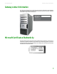
www.gateway.com Gateway contact information Gateway contact information The label on the side of your computer case contains information that identifies your computer model and serial number. Gateway Customer Care will need this information if you call for assistance. Web site: gate way .
CHAPTER 1: About This Reference 4 www.gateway.
CHAPTER 2 Hardware Basics • Front • Back 5
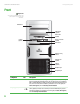
CHAPTER 2: Hardware Basics www.gateway.com Front Important Your computer hardware options and port locations may vary from this illustration.
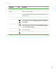
www.gateway.com Component Front Icon Description Diskette drive (optional) Insert a standard 3.5-inch diskette into the diskette drive. Memory card reader (optional) Insert a memory card from a digital camera, MP3 player, PDA, cellular telephone, or other devices into the memory card reader. Power button Press this button to turn the power on or off. You can also configure the power button to operate in Standby/Resume mode or Hibernate mode.
CHAPTER 2: Hardware Basics www.gateway.com Back Important Your computer hardware options and port locations may vary from this illustration. Your computer includes the following components.
www.gateway.com Component Back Icon Description IEEE 1394 port (optional) Plug IEEE 1394 (also known as Firewire® or i.Link®) devices (such as a digital camcorder) into this 6-pin IEEE 1394 port. For more information, see your User Guide, which is available on your hard drive. To access this guide, click Start, All Programs, then click Gateway Documentation. Parallel port (optional) Plug a parallel device (such as a printer) into this port.
CHAPTER 2: Hardware Basics Component 10 www.gateway.com Icon Description Serial port Plug a serial device into this port. For more information, see your User Guide, which is available on your hard drive. To access this guide, click Start, All Programs, then click Gateway Documentation. PS/2 keyboard port Plug a Personal System/2® (PS/2) keyboard into this port. PS/2 mouse port Plug a PS/2 mouse into this port. DVI monitor port (optional) Plug a digital monitor into this port.
CHAPTER 3 Maintenance Basics • Preventing static electricity discharge • Opening the case • Closing the case • Adding or replacing memory • Replacing the system battery • Adding or replacing a CD or DVD drive • Adding or replacing an optional diskette drive • Adding or replacing the memory card reader • Adding or replacing a hard drive • Replacing the front fan • Replacing the rear fan • Replacing the power supply • Replacing the heat sink and processor • Replacing the I/O board • Adding or replacing an exp
CHAPTER 3: Maintenance Basics www.gateway.com Preventing static electricity discharge Warning To avoid exposure to dangerous electrical voltages and moving parts, turn off your computer and unplug the power cord and modem and network cables before opening the case. Warning To prevent risk of electric shock, do not insert any object into the vent holes of the power supply. The components inside your computer are extremely sensitive to static electricity, also known as electrostatic discharge (ESD).
www.gateway.com Opening the case Important Your computer hardware options and port locations may vary from these illustrations. 5 Lift the cover release lever. 6 Swing the side panel away from the computer, then lift the panel away from the computer.
CHAPTER 3: Maintenance Basics www.gateway.com Removing the front bezel To remove the front bezel: ■ Push on the three spring tabs, grasp the right side of the front bezel, then pull the bezel out and away from the case. Closing the case Replacing the front bezel To replace the front bezel: 1 Insert the tabs on the left side of the bezel into the slots in the left side of the computer.
www.gateway.com Adding or replacing memory Replacing the side panel To replace the side panel: 1 Make sure that all of the internal cables are arranged inside the computer so they will not be pinched when you close the computer. Important Your computer hardware options and port locations may vary from this illustration. 2 Insert the bottom edge of the side panel into the inside bottom edge of the computer, then swing the side panel in toward the top of the computer to secure it into place.
CHAPTER 3: Maintenance Basics www.gateway.com 3 Find the memory module banks on your system board. 4 If you are removing a DIMM from the memory module bank, gently pull the plastic tabs away from the sides of the memory module and remove it. - OR If you are adding a DIMM to an empty memory module bank, gently pull the plastic tabs away from the sides of the memory module bank. 5 Align the notches on the new DIMM with the notches on the memory module bank and press the module firmly into the bank.
www.gateway.com Replacing the system battery Replacing the system battery Warning Danger of explosion if battery is incorrectly replaced. Replace only with the same or equivalent type recommended by the manufacturer. Dispose of used batteries according to local hazardous materials regulations. If the computer clock does not keep time or the settings in the BIOS Setup utility are not saved when you turn off your computer, replace the system battery.
CHAPTER 3: Maintenance Basics www.gateway.com 15 In the BIOS Setup utility, restore any settings that you wrote down in Step 3. 16 Save all your settings and exit the BIOS Setup utility. Adding or replacing a CD or DVD drive To add or replace a CD or DVD drive: 1 Remove the side panel by following the instructions in “Removing the side panel” on page 12. 2 Remove the front bezel by following the instructions in “Removing the front bezel” on page 14.
www.gateway.com Adding or replacing an optional diskette drive 7 If you are replacing a drive, note any jumper settings on the old drive and set the jumpers on the new drive to be the same. If you are installing a new drive, follow the manufacturer’s instructions. 8 Slide the new drive into the drive bay, line up the thumbscrew hole on the drive bay with the screw hole on the drive, then slide the drive release latch toward the front of the computer to lock the drive into place.
CHAPTER 3: Maintenance Basics www.gateway.com 5 Slide the drive release latch back to unlock the drive, then slide the drive forward and out of the drive bay. 6 Slide the new drive into the drive bay. 7 Slide the drive release latch forward to lock the drive into place. You do not need to replace the thumbscrew because it was originally installed for shipping purposes. 8 Reconnect the drive cables using your notes from Step 3. If you are installing a new drive, follow the manufacturer’s instructions.
www.gateway.com Adding or replacing the memory card reader 5 Remove the thumbscrew holding the card reader in the drive bay. Thumbscrew 6 Slide the drive release latch back to release the card reader, then slide the card reader out of the case. 7 Note any jumper settings on the old card reader and set the new card reader jumpers the same. If you are installing a new card reader, refer to the instructions that came with the card reader.
CHAPTER 3: Maintenance Basics www.gateway.com Adding or replacing a hard drive Caution Before replacing the hard drive in your computer, you must create restore discs and print a copy of the restore chapter in the User Guide. If this is not done, you will not be able to reinstall your drivers and programs. To add or replace a hard drive: 1 Create restore discs and print the restore chapter in the User Guide. To access the User Guide, click Start, All Programs, then click Gateway Documentation.
www.gateway.com Replacing the front fan 7 Note any jumper settings on the old drive and set the jumper on the new drive to be the same. If you are installing a new drive, follow the manufacturer’s instructions. Jumper 8 Slide the new drive into the drive bay, then secure it in the drive bay by sliding the drive release latch in toward the computer. 9 If you are replacing a drive, reconnect the drive cables using your notes from Step 4.
CHAPTER 3: Maintenance Basics www.gateway.com 2 Remove the fan cover by squeezing the top and bottom, then pulling it out. 1 2 1 3 Disconnect the fan cable from the system board. The location of the fan connection may vary, so trace the fan cable from the fan to the system board. 4 Remove the fan mount by pressing in on the flat area near the front, then rotating the fan mount back. 2 1 5 Slide the old fan out of the fan mount. 6 Slide the new fan into the fan mount.
www.gateway.com Replacing the rear fan Caution Be careful not to catch the wires connecting the power button to the system board when rotating the fan mount. A notch has been provided for routing these wires. 7 Insert the tabs on the rear of the fan mount into the slots provided, then rotate the mount into place. The mount should lock into place. 8 Reconnect the fan cable to the system board. 9 Replace the fan cover.
CHAPTER 3: Maintenance Basics Important Your computer hardware options and port locations may vary from this illustration. www.gateway.com 3 Remove the four screws that secure the fan to the inside back of the computer, then remove the fan from inside the computer. Note the orientation of the fan (which way it blows) and install the new fan the same way.
www.gateway.com Replacing the heat sink and processor Important Your computer hardware options and port locations may vary from this illustration. 3 Remove the three screws that secure the power supply to the computer. Screws 4 Slide the power supply away from the back of the computer, then lift up. 5 Install the new power supply into the case, then install the three screws to secure the power supply to the case. 6 Reconnect the power supply cables using your notes from Step 2.
CHAPTER 3: Maintenance Basics www.gateway.com 3 Remove the fan cover by squeezing the top and bottom, then pulling it out. 1 2 1 4 Loosen the four screws that secure the heat sink to the system board, then remove the heat sink. Caution The heat sink has Thermal Interface Material (TIM) located on the bottom of it. Use caution when you remove the old heat sink or unpack the new heat sink so you do not damage the TIM.
www.gateway.com Replacing the I/O board 8 Place the heat sink on the system board, then tighten the screws that secure it to the system board. 9 Replace the fan cover. 10 Return your computer to its upright position. 11 Replace the side panel by following the instructions in “Replacing the side panel” on page 15. Replacing the I/O board Tips & Tricks You need a Phillips screwdriver to replace the I/O board.
CHAPTER 3: Maintenance Basics www.gateway.com 4 Remove the screw that secures the front I/O panel board to the computer, then remove the I/O panel board by pushing it toward the back of the computer. Screw 5 Disconnect the cable from the old I/O panel board and connect it to the new I/O panel board. 6 Insert the new I/O panel board into the computer, then replace the screw. 7 Place the front I/O assembly onto the computer, then replace the screw.
www.gateway.com Adding or replacing an expansion card Adding or replacing an expansion card To add or replace an expansion card: 1 Remove the side panel by following the instructions in “Removing the side panel” on page 12. Important Your computer hardware options and port locations may vary from this illustration. 2 Remove the thumbscrew from the expansion card cover. Expansion card cover Thumbscrew 3 For more stability, place your computer on its side.
CHAPTER 3: Maintenance Basics Caution Do not touch the contacts on the bottom part of the expansion card. Touching the contacts can cause electrostatic damage to the card. www.gateway.com 6 Install the new card into the expansion slot. You can slightly seesaw the card end-to-end to help insert the card, but do not bend the card sideways. 7 Replace the thumbscrew in the expansion card cover.
www.gateway.com Replacing the system board 5 Remove the fan cover by squeezing the top and bottom, then pulling it out. 1 2 1 6 Find the memory module banks on your system board. 7 Gently pull the plastic tabs away from the sides of the memory modules, then remove them. Caution The heat sink has Thermal Interface Material (TIM) located on the bottom of it. Use caution when you remove the old heat sink or unpack the new heat sink so you do not damage the TIM.
CHAPTER 3: Maintenance Basics www.gateway.com 10 Remove the seven system board screws. Screws Screws 11 Lift the system board up and out of the case. 12 Align the new system board on the standoffs and secure it into the computer case with the screws. 13 If your replacement system board does not include a processor, go to Step 14. -ORIf your replacement system board includes a processor, go to Step 17.
www.gateway.com Replacing the system board 18 Place the heat sink over the processor, then tighten the screws that secure it to the system board. 19 Align the notches on the memory modules with the notches on the memory module banks and press the modules firmly into the banks. The tabs on the sides of the memory modules should secure the memory modules automatically. When a module is secure, you hear a click. Caution Do not touch the contacts on the bottom part of the expansion card.
CHAPTER 3: Maintenance Basics 36 www.gateway.
APPENDIX A Safety, Regulatory, and Legal Information • Important safety information • Regulatory compliance statements • Environmental information • Notices 37
APPENDIX A: Safety, Regulatory, and Legal Information www.gateway.com Important safety information Your Gateway system is designed and tested to meet the latest standards for safety of information technology equipment. However, to ensure safe use of this product, it is important that the safety instructions marked on the product and in the documentation are followed. Warning Always follow these instructions to help guard against personal injury and damage to your Gateway system.
www.gateway.com Regulatory compliance statements United States of America Federal Communications Commission (FCC) Unintentional emitter per FCC Part 15 This device has been tested and found to comply with the limits for a Class B digital device, pursuant to Part 15 of the FCC rules. These limits are designed to provide reasonable protection against harmful interference in a residential installation.
APPENDIX A: Safety, Regulatory, and Legal Information www.gateway.
www.gateway.com Environmental information The product you have purchased contains extracted natural resources that have been used in the manufacturing process. This product may contain substances known to be hazardous to the environment or to human health. To prevent releases of harmful substances into the environment and to maximize the use of our natural resources, Gateway provides the following information on how you can responsibly recycle or reuse most of the materials in your “end of life” product.
APPENDIX A: Safety, Regulatory, and Legal Information 42 www.gateway.
Index digital camera 6, 7, 9, 10 digital coaxial audio 9 digital video camera 7, 9 Ethernet 8 external audio 9 external speakers 9 Firewire 7, 9 front speaker 9 headphone 9 i.
Index memory 15 memory card reader 20 power supply 26 processor 27 rear fan 25 side panel 12 system battery 17 system board 32 J jacks See connections K keyboard PS/2 port 10 USB port 6, 7, 9 L label Microsoft Certificate of Authenticity 3 product 3 line in jack 9 line out jack 9 M memory adding 15 installing 15 replacing 15 memory card reader locating 6 replacing 20 microphone jack 7, 9 Microsoft Certificate of Authenticity 3 modem jack 10 monitor port 9 monitor port 10 mouse PS/2 port 10 USB port 6,
MAN GW BTX CONS HW REF R2 6/06