HARDWARE REFERENCE Gateway Computer
www.gateway.com Contents Contents Chapter 1: About This Reference . . . . . . . . . . . . . . . . . . . . . . . . . . . . . . . . . . . . . . . . . . . . . .1 About this guide . . . . . . . . . . . . . . . . . . . . . . . . . . . . . . . . . . . . . . . . . . . . . . . . . . . . . . . . Accessing the User Guide . . . . . . . . . . . . . . . . . . . . . . . . . . . . . . . . . . . . . . . . . . . . . . . . Gateway contact information . . . . . . . . . . . . . . . . . . . . . . . . . . . . . . . . . . . . .
Contents ii www.gateway.
CHAPTER 1 About This Reference • Accessing the User Guide • Gateway contact information • Microsoft Certificate of Authenticity 1
CHAPTER 1: About This Reference www.gateway.com About this guide This guide includes information and maintenance instructions that are specific to your model of Gateway computer. For all other computer information, see your online User Guide. Accessing the User Guide In addition to this guide, the User Guide has been included on your hard drive.
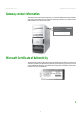
www.gateway.com Gateway contact information Gateway contact information The label on the side of your computer case contains information that identifies your computer model and serial number. Gateway Customer Care will need this information if you call for assistance. Onlin Tech e supp Supp Tech Supp ort: ort Phon ort e: Hou rs: (U.S. (Can) ada) 900439 4 Online support: Tech Support Phone: (U.S.
CHAPTER 1: About This Reference 4 www.gateway.
CHAPTER 2 Hardware Features • Front • Back 5
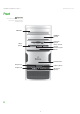
CHAPTER 2: Hardware Features www.gateway.com Front Important Your computer hardware options and port locations may vary from the illustration below.
www.gateway.com Component DVD/CD drive Front Icon Description Use this drive to listen to audio CDs, install games and programs, watch DVDs, and store large files onto recordable discs (depending on drive type). This drive may be a CD, recordable CD, DVD, or recordable DVD drive. To identify your drive type and for more information about your drive, see your user guide.
CHAPTER 2: Hardware Features www.gateway.com Back Your computer matches one of the two following illustrations, and includes the components listed. Important Your computer hardware options and port locations may vary from the illustrations below. Power connector Voltage switch Case cover thumbscrew Headphone/front speaker jack Audio in/side speaker jack Surround left/right speaker jack Microphone jack S/PDIF jack (optional) Center/subwoofer jack Ethernet (network) jack IEEE 1394/FireWire™/ i.
www.gateway.com Back Power connector Voltage switch Case cover thumbscrew Headphone/front speaker jack Audio in/side speaker jack Surround left/right speaker jack Ethernet (network) jack IEEE 1394/FireWire™/ i.
CHAPTER 2: Hardware Features www.gateway.com Available ports may vary, depending on your model. Component 10 Icon Description Power connector Plug the power cord into this connector. Case cover thumbscrews Remove these screws before opening the case. Audio input (Line in) jack (blue plug) -ORSide speaker jack This jack is user configurable for one of the following: Stereo in: Plug an external audio input source (such as a stereo) into this jack so you can record sound on your computer (Default).
www.gateway.com Component Back Icon Description S/PDIF optical audio jack Plug an S/PDIF optical audio connection to this jack. Rear speaker jack (black plug) Plug your right rear and left rear speakers into this jack. For information on configuring this jack, see your user guide. USB ports Plug USB (Universal Serial Bus) devices (such as a USB Iomega™ Zip™ drive, printer, scanner, camera, keyboard, or mouse) into these ports. For more information, see your user guide.
CHAPTER 2: Hardware Features 12 www.gateway.
CHAPTER 3 Maintenance Basics • Preventing static electricity discharge • Opening the case • Closing the case • Installing memory • Replacing the system battery • Adding or replacing a CD or DVD drive • Replacing the memory card reader • Adding or replacing a hard drive • Replacing the front fan • Replacing the rear fan • Replacing the power supply • Replacing the heat sink and processor • Replacing the I/O board • Adding or replacing an expansion card • Replacing the system board 13
CHAPTER 3: Maintenance Basics www.gateway.com Preventing static electricity discharge Warning To avoid exposure to dangerous electrical voltages and moving parts, turn off your computer and unplug the power cord and modem and network cables before opening the case. Caution ESD can permanently damage electrostatic discharge-sensitive components in your computer. Prevent ESD damage by following ESD guidelines every time you open the computer case.
www.gateway.com Opening the case 4 Remove the two thumbscrews on the side panel cover. Thumbscrews 5 Swing the side panel away from the back of your computer, then pull the panel off. Removing the front bezel To remove the front bezel: ■ Press the three bezel retention tabs, then swing the right side of the front bezel away from the computer and remove it.
CHAPTER 3: Maintenance Basics www.gateway.com Closing the case Replacing the front bezel To replace the front bezel: 1 Slide the tabs on the left side of the bezel into the slots in the left side of the computer. 2 Swing the right side of the bezel in to insert the tabs on the right side of the bezel into the slots on the right side of the computer. 3 Press the right side of the bezel firmly until it snaps into place.
www.gateway.com Installing memory Installing memory When you upgrade the computer memory, make sure that you install the correct type of memory module for your computer. Your computer uses DIMM memory. To install or replace DIMM memory: 1 Remove the side panel by following the instructions in “Removing the side panel” on page 14. 2 For more stability, place your computer on its side. To avoid scratching the case, place it on a towel or other non-abrasive surface.
CHAPTER 3: Maintenance Basics www.gateway.com 8 Reconnect the cables and the power cord. 9 Turn on your computer. Windows starts and the Windows desktop appears. 10 Click Start, Control Panel, then click Performance and Maintenance (if in Category view). Click/Double-click System. The amount of memory in your computer is shown at the bottom of the System Properties dialog box in the General tab. Replacing the system battery Warning Danger of explosion if battery is incorrectly replaced.
www.gateway.com Adding or replacing a CD or DVD drive 9 Make sure that the positive (+) side of the new battery is facing up, then press the battery into the socket until it snaps into place. 10 Replace the side panel by following the instructions in “Replacing the side panel” on page 16. 11 Reconnect all external cables and the power cord. 12 Turn on your computer. 13 Open the BIOS Setup utility. 14 In the BIOS Setup utility, restore any settings that you wrote down in Step 3.
CHAPTER 3: Maintenance Basics www.gateway.com 6 Remove the two drive retention screws, then slide the drive forward and out of the drive bay. Drive retention screws 7 Slide the new drive into the drive bay, line up the screw holes on the drive bay with the screw holes on the drive, then replace the two drive retention screws. Drive retention screws 8 Reconnect the drive cables using your notes from Step 4.
www.gateway.com Adding or replacing a hard drive 4 Remove the two drive retention screws, disconnect the card reader’s data cable from the system board, then slide the drive forward and out of the drive bay. Screws 5 Slide the card reader out of the case. 6 Slide the new card reader into the bay from the front of the case. Screws 7 Use the screws you removed previously to secure the card reader to the bay. 8 Connect the new card reader’s data cable to the system board.
CHAPTER 3: Maintenance Basics www.gateway.com 3 Disconnect the drive cables, noting their locations and orientation. (You will reconnect the cables after you install the new drive.) 4 Pull the front fan assembly away from the system board, then remove it. 5 Disconnect the fan cable from the system board.
www.gateway.com Adding or replacing a hard drive 6 Remove the hard drive bay screw. Hard drive bay screw 7 Remove the hard drive bay from your computer. You may need to work the bay out of your computer by rocking the bay back and forth. 8 If you are replacing an old drive, remove the four screws that secure the hard drive to the hard drive bay, then remove the hard drive from the bay.
CHAPTER 3: Maintenance Basics www.gateway.com 10 If you are replacing a drive, note any jumper settings on the old drive and set the jumper on the new drive to be the same. If you are adding a new drive, set the jumper as instructed by the drive’s user guide. Jumper 11 Slide the new drive into the drive bay, then secure the drive to the bay using the four screws you removed previously.
www.gateway.com Replacing the front fan Replacing the front fan Tips & Tricks You need a Phillips screwdriver to replace the front fan. To replace the front fan: 1 Remove the side panel by following the instructions in “Removing the side panel” on page 14. 2 Pull the front fan away from the system board, then remove it. 3 Disconnect the fan cable from the system board. 4 Connect the new fan cable to the system board, then insert the new fan into place.
CHAPTER 3: Maintenance Basics www.gateway.com Replacing the rear fan Tips & Tricks You need a Phillips screwdriver to replace the rear fan. To replace the rear fan: 1 Remove the side panel by following the instructions in “Removing the side panel” on page 14. 2 Disconnect the fan from the system board. 3 Remove the four screws on the outside of the case that secure the fan to the back of the case, then remove the fan.
www.gateway.com Replacing the power supply Replacing the power supply Tips & Tricks You need a Phillips screwdriver to replace the power supply. To replace the power supply: 1 Remove the side panel by following the instructions in “Removing the side panel” on page 14. 2 Disconnect the power supply cables from all components (such as hard drives, CD or DVD drives, and the system board), noting their locations and orientation. (You will reconnect the cables after you install the new power supply.
CHAPTER 3: Maintenance Basics www.gateway.com Replacing the heat sink and processor Tips & Tricks You need a Phillips screwdriver to replace the heat sink. To replace the heat sink and processor: 1 Remove the side panel by following the instructions in “Removing the side panel” on page 14. 2 For more stability, place your computer on its side. To avoid scratching the case, place it on a towel or other non-abrasive surface. 3 Pull the front fan away from the system board, then remove it.
www.gateway.com Replacing the heat sink and processor 5 Loosen the four screws that secure the heat sink to the system board, then remove the heat sink and place it on a stable surface with the flat surface of the heat sink (the side with the thermal grease) up. Screws Screws 6 Release the processor by pushing down on the lever and then lifting it completely up. 7 Remove the processor from the system board.
CHAPTER 3: Maintenance Basics www.gateway.com Replacing the I/O board Important The color and shape of your replacement I/O panel may vary from your original I/O panel.. To replace the front I/O panel: 1 Remove the side panel by following the instructions in “Removing the side panel” on page 14. 2 Remove the bezel by following the instructions in “Removing the front bezel” on page 15. 3 Disconnect the cable from the I/O panel.
www.gateway.com Adding or replacing an expansion card Adding or replacing an expansion card To add or replace an expansion card: 1 Remove the side panel by following the instructions in “Removing the side panel” on page 14. 2 If you are replacing an expansion card, go to the next step. If you are adding a new expansion card, go to Step 4. 3 Disconnect any cables that are attached to the card, noting their locations and orientation. (You may need to reconnect the cables after you install the new card.
CHAPTER 3: Maintenance Basics www.gateway.com Replacing the system board To replace the system board: 1 Remove the side panel by following the instructions in “Removing the side panel” on page 14. 2 Disconnect any expansion card cables from the cards and from the system board, noting their locations and orientation. (You will reconnect the cables after you reinstall the cards.) You can also mark the cables with tape labels to simplify reconnecting cables later. 3 Open the card retention lever.
www.gateway.com Replacing the system board 5 Pull the front fan away from the system board, then remove it. 6 Disconnect the fan cable from the system board. 7 Find the memory module banks on your system board. 8 Gently pull the plastic tabs away from the sides of the memory modules, then remove them. 9 Disconnect the power and data cables from the system board, noting their locations and orientation. (You will reconnect the cables after you install the new board.
CHAPTER 3: Maintenance Basics www.gateway.com 10 Remove the three screws that secure the power supply to your computer. Screws 11 Slide the power supply away from the back of your computer, then pull it down and remove it. 12 Remove the seven system board screws. Screws Screws 13 Lift the system board up and out of the case. 14 Align the new system board on the screw holes in the case, then secure it into the case with the screws.
www.gateway.com Replacing the system board 16 Loosen the four screws that secure the heat sink to the system board, then remove the heat sink and place it on a stable surface with the flat surface of the heat sink (the side with the thermal grease) up. Screws Screws 17 Release the processor from the old system board by pushing down on the lever and then lifting it completely up. 18 Remove the processor from the old system board.
CHAPTER 3: Maintenance Basics www.gateway.com 25 Reinstall any expansion cards you removed. 26 Replace the side panel by following the instructions in “Replacing the side panel” on page 16.
CHAPTER 4 Configuring Drives for RAID • About RAID • Configuring RAID • Getting help 37
CHAPTER 4: Configuring Drives for RAID www.gateway.com About RAID RAID (Redundant Array of Inexpensive/Independent Disks) lets your computer use multiple hard drives more efficiently. Your computer supports RAID 0, RAID 1, RAID 5, and RAID 10. RAID for performance RAID 0 lets your computer see multiple hard drives as a single drive. This type of RAID can increase file access speeds, which is important if you work with video editing, sound editing, and high-performance games.
www.gateway.com About RAID RAID for security RAID 1 maintains a complete copy of a file set on each physical hard drive in the array. Because each hard drive has a full copy of all files, your data and applications are completely backed up. Maintaining simultaneous, complete copies of files across multiple hard drives is called mirroring. File reading performance (seek time) is increased using the same methods that RAID 0 uses, although writing speed is the same as if writing to a single hard drive.
CHAPTER 4: Configuring Drives for RAID www.gateway.com Configuring RAID Enabling RAID Although your computer is capable of using RAID, the RAID feature is not yet enabled. To enable RAID on your computer: 1 Start (or restart) your computer. 2 As soon as your computer turns on and the Gateway logo appears on the screen, press F2. The BIOS Setup utility opens. 3 Select the Advanced menu, then select Drive Configuration. 4 Change the ATA/IDE Mode to Enhanced. 5 Change the SATA mode to RAID.
www.gateway.com Configuring RAID 2 While the RAID option screen is open, press CTRL+i. The Matrix Storage Manager opens. 3 Highlight 1. Create RAID Volume, then press ENTER. The CREATE VOLUME MENU opens. 4 Change the following settings: Name—Type a volume name (up to 16 characters) or use the default name, then press ENTER. ■ RAID Level—Press ↑ or ↓ to select the RAID level, then press ENTER.
CHAPTER 4: Configuring Drives for RAID www.gateway.com Deleting a RAID volume Deleting a RAID volume deletes all files on that volume, including operating system files. To delete a RAID volume: 1 Start (or restart) your computer. During startup, the RAID option screen appears. 2 While the RAID option screen is open, press CTRL+i. The Matrix Storage Manager opens.
www.gateway.com Getting help Getting help For more information on RAID concepts, configuration, and maintenance, search for RAID FAQ information on the Gateway Technical Support Web site (support.gateway.com) and the Intel Support & Downloads Web site (support.intel.com). © 2006 Gateway, Inc. All rights reserved. Gateway and eMachines are trademarks or registered trademarks of Gateway, Inc. in the United States and other countries.
CHAPTER 4: Configuring Drives for RAID 44 www.gateway.
www.gateway.com Index Index external audio 10 external speakers 10 Firewire 7, 10 front speaker 10 headphone 10 i.
Index www.gateway.
MAN 6BAY MBTX CONS HW REF R2 7/06