Your Gateway Plasma TV user'sguide Setting up Troubleshooting
www.gateway.
09141.book Page i Tuesday, May 20, 2003 2:27 PM Contents 1 Introducing Your Gateway Plasma TV . . . . . . . . . . . . . . . . . . . . . . . . . . . 1 Features . . . . . . . . . . . . . . . . . . . . . . . . . . . . . . . . . . . . . . . . . . . . . . . . . . . . . . . . . . . 2 Important Safeguards . . . . . . . . . . . . . . . . . . . . . . . . . . . . . . . . . . . . . . . . . . . . . . . . 3 Package contents . . . . . . . . . . . . . . . . . . . . . . . . . . . . . . . . . . . . . . . . . . . . . . . .
09141.book Page ii Tuesday, May 20, 2003 2:27 PM B Safety, Regulatory, and Legal Information . . . . . . . . . . . . . . . . . . . . . . .53 Index. . . . . . . . . . . . . . . . . . . . . . . . . . . . . . . . . . . . . . . . . . . . . . . . . . . . . . . . . . . . . . .
09141.book Page 1 Tuesday, May 20, 2003 2:27 PM Introducing Your Gateway Plasma TV 1 This chapter provides basic information about your Gateway Plasma TV.
09141.
09141.book Page 3 Tuesday, May 20, 2003 2:27 PM Important Safeguards Important Safeguards Warning Risk of electric shock - Do not open To reduce the risk of electric shock, do no remove the back cover. There are no user-serviceable parts inside. Removing the back cover voids the warranty. Have your plasma TV repaired by qualified service personnel only. Warnings and precautions ■ Do not place your hands, face, or objects close to the ventilation openings of your plasma TV.
09141.book Page 4 Tuesday, May 20, 2003 2:27 PM Chapter 1: Introducing Your Gateway Plasma TV ■ Do not place your plasma TV on a bed, sofa, rug, or other similar surfaces. Never place your plasma TV near or over a radiator or heat source. Do not install your plasma TV in an enclosed area unless correct ventilation is provided. ■ Your plasma TV should be operated from the type of power source indicated on the label.
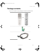
09141.book Page 5 Tuesday, May 20, 2003 2:27 PM Package contents Package contents Along with your plasma TV, the packaging box contains the following items: Remote control - OR - Two AA batteries Power cord www.gateway.
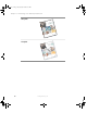
09141.book Page 6 Tuesday, May 20, 2003 2:27 PM Chapter 1: Introducing Your Gateway Plasma TV User guide Remote control user guide 6 www.gateway.
09141.book Page 7 Tuesday, May 20, 2003 2:27 PM Package contents You can purchase these optional accessories for your plasma TV: ■ Wall mount kit. The wall mount kit contains all of the required hardware for mounting your plasma TV on your wall. (Gateway recommends you use a qualified installer.) For more information, see the Wall Mount Installation Guide at support.gateway.com. ■ Cable kits.
09141.book Page 8 Tuesday, May 20, 2003 2:27 PM Chapter 1: Introducing Your Gateway Plasma TV Turning on the main power To turn on the main power: 1 Connect the power cord to the power cord connector on the back of your plasma TV, then plug the other end of the power cord into a correctly grounded electrical outlet or surge protector. - OR - 8 www.gateway.
09141.book Page 9 Tuesday, May 20, 2003 2:27 PM Turning on the main power 2 Press the MAIN POWER button. The Status LED on the front panel turns yellow and your plasma TV is ready to turn on. - OR - Warning If you will be away for an extended period of time, turn off your plasma TV with the MAIN POWER button instead of using the remote control or front panel POWER button.
09141.book Page 10 Tuesday, May 20, 2003 2:27 PM Chapter 1: Introducing Your Gateway Plasma TV Front panel controls Volume and Adjust +/- 10 Menu +/- Input Remote Control Sensor www.gateway.
09141.book Page 11 Tuesday, May 20, 2003 2:27 PM Front panel controls Button Description Volume and Adjustment +/– VOL/ADJ. Increases or decreases the volume and adjusts on-screen display (OSD) options. Menu +/– MENU. Opens the OSD. Input Switches between available input sources. Remote control sensor Receives signals from the remote control. Do not block. Status LED ■ ■ ■ Power Not lit - No AC power detected. The main power button is off or the power cord is not connected.
09141.book Page 12 Tuesday, May 20, 2003 2:27 PM Chapter 1: Introducing Your Gateway Plasma TV Back panel connections Audio and video connections RGB and DVI connections Connector Description Audio and video connections See “Audio and video connections” on page 13. RGB and DVI connections See “RGB and DVI connections” on page 14. 12 www.gateway.
09141.book Page 13 Tuesday, May 20, 2003 2:27 PM Back panel connections Audio and video connections Antenna DVI Audio In Subwoofer External Speaker Switch RGB Audio In Video 1/ Audio In Component Video 1/ Audio In Audio Out S-Video/ Audio In Component Video 2/ Audio In Connector Description Antenna Connects to a VHF/UHF antenna. DVI Audio In Connects to the audio on a DVI device. Video 1/Audio In Connects to a composite audio/video device, such as a VCR.
09141.book Page 14 Tuesday, May 20, 2003 2:27 PM Chapter 1: Introducing Your Gateway Plasma TV RGB and DVI connections RGB In 14 RGB Out DVI In RS-232 Connector Description RGB In Connects to an RGB video device, such as a computer or set-top box. RGB Out Connects to an external RGB monitor. DVI In Connects to a DVI video device, such as a computer or set-top box.
09141.book Page 15 Tuesday, May 20, 2003 2:27 PM Connecting Components 2 Read this chapter to learn how to connect: ■ DVD players ■ HDTV decoder set-top boxes ■ VCRs ■ Off-air TV and cable TV ■ External audio devices ■ Computers Warning Before connecting any external components, turn off your plasma TV using the remote control or front panel button, then turn off the main power using the MAIN POWER button on the back of your plasma TV.
09141.book Page 16 Tuesday, May 20, 2003 2:27 PM Chapter 2: Connecting Components Understanding video connections Your plasma TV has four types of standard video connections. You should use the best connection available to get the best display. For example, if your DVD player supports a component video connection, connect the DVD player to your plasma TV using component video instead of composite video or S-Video. Connection Quality Cable and Connector Description Basic Coaxial (RF).
09141.book Page 17 Tuesday, May 20, 2003 2:27 PM Connecting your DVD player Connecting your DVD player To connect your DVD player using component video: 1 Connect the green-colored Y jack on the back of your DVD player to the green-colored Y1 jack on the back of your plasma TV. 2 Connect the red-colored PR or CR jack on the back of your DVD player to the red-colored PR1/CR1 jack on the back of your plasma TV.
09141.book Page 18 Tuesday, May 20, 2003 2:27 PM Chapter 2: Connecting Components To connect your DVD player using S-Video: 18 1 Connect the S-Video jack on the back of your DVD player to the S-VIDEO jack on the back of your plasma TV. 2 Connect the red (R) and white (L) audio jacks on the back of your DVD player to the R and L audio-in jacks on the back of your plasma TV. www.gateway.
09141.book Page 19 Tuesday, May 20, 2003 2:27 PM Connecting your DVD player To connect your DVD player using composite video: 1 Connect the yellow video jack on the back of your DVD player to the yellow VIDEO 1 jack on the back of your plasma TV. 2 Connect the red (R) and white (L) audio jacks on the back of your DVD player to the R and L audio-in jacks on the back of your plasma TV. www.gateway.
09141.book Page 20 Tuesday, May 20, 2003 2:27 PM Chapter 2: Connecting Components Connecting your HDTV decoder set-top box To connect your HDTV decoder set-top box using component video: 20 1 Connect the green Y jack on the back of your HDTV set-top box to the green Y2 jack on the back of your plasma TV. 2 Connect the red PR or CR jack on the back of your HDTV set-top box to the red PR2/CR2 jack on the back of your plasma TV.
09141.book Page 21 Tuesday, May 20, 2003 2:27 PM Connecting your HDTV decoder set-top box To connect your HDTV decoder set-top box using RGB video: 1 Connect the 15-pin D-Sub RGB jack on the back of your HDTV set-top box to the RGB-IN jack on the back of your plasma TV. 2 Connect the red (R) and white (L) audio-out jacks on the back of your HDTV set-top box to the R and L audio-in jacks on the back of your plasma TV.
09141.book Page 22 Tuesday, May 20, 2003 2:27 PM Chapter 2: Connecting Components Connecting your VCR or video camera To connect your VCR or video camera using S-Video: - OR - 22 1 Connect the S-Video jack on the back of your VCR or video camera to the S-VIDEO jack on the back of your plasma TV. 2 Connect the red (R) and white (L) audio jacks on the back of your VCR or video camera to the R and L audio-in jacks on the back of your plasma TV. www.gateway.
09141.book Page 23 Tuesday, May 20, 2003 2:27 PM Connecting your VCR or video camera To connect your VCR or video camera using composite video: - OR - 1 Connect the yellow video jack on the back of your VCR or video camera to the yellow VIDEO 1 jack on the back of your plasma TV. 2 Connect the red (R) and white (L) audio jacks on the back of your VCR or video camera to the R and L audio-in jacks on the back of your plasma TV. www.gateway.
09141.book Page 24 Tuesday, May 20, 2003 2:27 PM Chapter 2: Connecting Components To connect your VCR using coaxial (RF) audio and video: ■ Connect the “output to TV” (RF out or Antenna out) jack on the back of your VCR to the ANT jack on the back of your plasma TV. If you have an off-air antenna or cable box, connect your off-air antenna or cable TV cable to the ANT connector on the back of your VCR.
09141.book Page 25 Tuesday, May 20, 2003 2:27 PM Connecting off-air TV or cable TV Connecting off-air TV or cable TV To connect off-air TV or cable TV using coaxial (RF) audio and video: - OR ■ Connect the coaxial (RF) connector from your antenna or cable box to the ANT connector on the back of your plasma TV. If you have connected a VCR to the ANT connector on the back of your plasma TV, connect your off-air TV or cable TV cable to the ANT connector on the back of your VCR.
09141.book Page 26 Tuesday, May 20, 2003 2:27 PM Chapter 2: Connecting Components Connecting external amplified speakers You can connect your plasma TV to a set of external, amplified speakers using the AUDIO OUT jacks located on the back of your plasma TV. If your external speakers have remote turn-on/off capability, connect the external speaker switch.
09141.book Page 27 Tuesday, May 20, 2003 2:27 PM Connecting an external receiver or amplifier Connecting an external receiver or amplifier You can connect an external amplifier to your plasma TV. Your plasma TV is equipped with a external speaker switch that can automatically send a remote turn-on/off signal to an external receiver or amplifier.
09141.book Page 28 Tuesday, May 20, 2003 2:27 PM Chapter 2: Connecting Components Connecting a subwoofer Your plasma TV has built-in speakers. You can enhance the bass response of your plasma TV’s sound by connecting an external, amplified subwoofer. To connect your subwoofer: 28 1 Connect the audio jack on the back of your subwoofer to the SUBWOOFER jack on the back of your plasma TV. 2 If your subwoofer accepts remote turn-on/off signals, connect the external speaker switch.
09141.book Page 29 Tuesday, May 20, 2003 2:27 PM Connecting a computer Connecting a computer To connect your computer using DVI video: 1 Connect the DVI connector on your computer to the DVI-In connector on the back of your plasma TV. 2 Connect the Audio Out jack on your computer to the DVI Audio In jacks on the back of your plasma TV. www.gateway.
09141.book Page 30 Tuesday, May 20, 2003 2:27 PM Chapter 2: Connecting Components To connect your computer using RGB video: 30 1 Connect the 15-pin D-Sub RGB connector on your computer to the RGB-IN connector on the back of your plasma TV. 2 Connect the Audio Out jack on your computer to the RGB Audio In jacks on the back of your plasma TV. www.gateway.
09141.book Page 31 Tuesday, May 20, 2003 2:27 PM Connecting a computer Connecting an external monitor A RGB loop-out (labeled RGB Out) lets you connect another RGB monitor. The RGB loop-out displays the same signal as the RGB In video input source. To connect your external monitor: ■ Connect the RGB connector on your monitor to the RGB Out connector on the back of your plasma TV.
09141.book Page 32 Tuesday, May 20, 2003 2:27 PM Chapter 2: Connecting Components 32 www.gateway.
09141.book Page 33 Tuesday, May 20, 2003 2:27 PM Adjusting Your Plasma TV Settings 3 Read this chapter to learn how to adjust your plasma TV settings from the on-screen display (OSD). You can also use your remote control to change some settings. For more information, see Your Gateway Remote Control User’s Guide.
09141.book Page 34 Tuesday, May 20, 2003 2:27 PM Chapter 3: Adjusting Your Plasma TV Settings Using the OSD Your plasma TV features an on-screen display (OSD) that lets you adjust and save contrast, brightness, and other settings. The TV saves changes you make to the settings, even if you turn off the TV. To adjust settings from the OSD: 34 1 2 Press the MENU + or – button on the front control panel. The OSD opens. 3 Press the MENU + or – button on the front control panel to select a menu option.
09141.book Page 35 Tuesday, May 20, 2003 2:27 PM Using the OSD OSD menus and options You can use these OSD menus and options to adjust various settings for your plasma TV. OSD Menu Description PICTURE – TV, AV1, AV2, Component 1, and Component 2 video sources INPUT SOURCE. Switches between available video input sources.
09141.book Page 36 Tuesday, May 20, 2003 2:27 PM Chapter 3: Adjusting Your Plasma TV Settings OSD Menu Description PICTURE – RGB/DVI video sources INPUT SOURCE. Switches between available video input sources. PICTURE SOUND PIP/POP TV OTHER INPUT SOURCE RGB CONTRAST 50 BRIGHTNESS 50 COLOR TEMPERATURE 6500D CLOCK PHASE 50 SCREEN WIDTH 16:9 V-SIZE 50 V-CENTER 50 H-WIDTH 50 POSITION 50 SELECT ITEM ADJUST VALUE CONTRAST. Adjusts the contrast of the picture. BRIGHTNESS.
09141.book Page 37 Tuesday, May 20, 2003 2:27 PM Using the OSD OSD Menu Description SOUND BASS. Adjusts the bass. The AUDIO OUTPUT option must be set to VARIABLE to adjust this setting. PICTURE SOUND PIP/POP TV OTHER 50 BASS 50 TREBLE 50 BALANCE STEREO SURROUND OFF BBE OFF BASS EXTENTION 50 VOLUME ON INNER SPKR FIXED AUDIO OUTPUT SELECT ITEM ADJUST VALUE TREBLE. Adjusts the treble. The AUDIO OUTPUT option must be set to VARIABLE to use this option. BALANCE.
09141.book Page 38 Tuesday, May 20, 2003 2:27 PM Chapter 3: Adjusting Your Plasma TV Settings OSD Menu Description PIP/POP PIP. Turns PIP mode on or off. When PIP is turned on, you can display two pictures at one time. One picture is displayed on the full screen and the other picture is displayed in a small window. The picture on the full screen is the main picture. The picture in the window is the sub-picture.
09141.book Page 39 Tuesday, May 20, 2003 2:27 PM Using the OSD OSD Menu Description PIP/POP (continued) POP. Turns POP mode on or off. When POP is turned on, the screen is split into two pictures. The picture on the left side of your screen is the main picture. The picture on the right side of the screen is the sub-picture.
09141.book Page 40 Tuesday, May 20, 2003 2:27 PM Chapter 3: Adjusting Your Plasma TV Settings OSD Menu Description TV CHANNEL. Changes the TV channel. PICTURE SOUND PIP/POP TV OTHER CHANNEL 12 CHANNEL STATUS NORMAL MTS STEREO CCD OFF V-CHIP OFF SET PARENTAL CODE DISABLE SET RATE DISABLE CH SEARCH DISABLE TUNER SOURCE CABLE BACKGROUND ON BACKGROUND COLOR BLUE SELECT ITEM ADJUST VALUE CHANNEL STATUS. Sets the status of the TV channel. NORMAL is the default.
09141.book Page 41 Tuesday, May 20, 2003 2:27 PM Using the OSD OSD Menu Description OTHER OSD TIMEOUT. Turns the OSD timer on and off. PICTURE SOUND PIP/POP TV OTHER OSD TIMEOUT OFF SET OSD TIME 5 OSD BRIGHTNESS 8 OSD BACKGROUND ON LANGUAGE ENGLISH SLEEP OFF SLEEP TIME 50 POWER SAVE OFF S/W VERSION 42L6-O724 INPUT H-FREQ [KHZ] 46.9 INPUT V-FREQ [KHZ] 75 SELECT ITEM ADJUST VALUE To avoid image burn-in, we recommend that you keep this timer turned on. SET OSD TIME.
09141.book Page 42 Tuesday, May 20, 2003 2:27 PM Chapter 3: Adjusting Your Plasma TV Settings 42 www.gateway.
09141.book Page 43 Tuesday, May 20, 2003 2:27 PM Maintenance and Troubleshooting 4 Read this chapter to learn how to maintain and troubleshoot your plasma TV.
09141.book Page 44 Tuesday, May 20, 2003 2:27 PM Chapter 4: Maintenance and Troubleshooting Cleaning and maintenance Cleaning the screen ■ Do not use substances such as glass cleaners, solvents, and thinners. ■ The screen of your plasma TV has been specially treated. Wipe the surface gently using only a cleaning cloth or a soft, lint-free cloth. ■ If the surface is particular dirty, use a soft cloth and water to clean the screen.
09141.book Page 45 Tuesday, May 20, 2003 2:27 PM Troubleshooting Avoiding image burn-in ■ Displaying the same stationary image over an extended period of time, such as a black bar, stock ticker, video game, or shopping channel logo, can leave a permanent ghost image (burn-in). Avoid burn-in by mixing your viewing patterns. Do not show the same stationary image for more than 15% of your total TV viewing in any one week. ■ Your warranty does NOT cover screen burn-in.
09141.book Page 46 Tuesday, May 20, 2003 2:27 PM Chapter 4: Maintenance and Troubleshooting The display image does not cover the entire screen ■ If your are using RGB mode, make sure that H-SIZE and V-SIZE in the OSD are set correctly. ■ If you are using TV, AV1, AV2, or component with 480i input, use the WIDE button on the remote control to scroll through various screen modes. You can see a picture but you cannot hear sound ■ Make sure that the volume is not turned down.
09141.book Page 47 Tuesday, May 20, 2003 2:27 PM Troubleshooting Telephone support If this troubleshooting information does not resolve your problem or if you have other questions relating to your plasma TV, call our Service Center at 888-737-MyGW (6949). For more information about Gateway, visit www.gateway.com. www.gateway.
09141.book Page 48 Tuesday, May 20, 2003 2:27 PM Chapter 4: Maintenance and Troubleshooting 48 www.gateway.
09141.book Page 49 Tuesday, May 20, 2003 2:27 PM Signal Frequency Information A Read this appendix for signal frequency information. For more information, see OSD menu “OTHER” on page 41.
09141.book Page 50 Tuesday, May 20, 2003 2:27 PM Appendix A: Signal Frequency Information TV, AV1, and AV2 inputs Horizontal (KHz) Vertical (Hz) Format 15.7 60 NTSC Video 15.6 50 PAL Video Component 1 and Component 2 inputs 50 Horizontal (KHz) Vertical (Hz) 15.7 60 NTSC Video 15.6 50 PAL Video 15.7 60 480i (SDTV) 31.5 60 480P (EDTV) 33.0 60 1080i (HDTV) 45.0 60 720P (HDTV) www.gateway.
09141.book Page 51 Tuesday, May 20, 2003 2:27 PM RGB and DVI inputs RGB and DVI inputs Mode Horizontal (KHz) Vertical (Hz) Format 1 31.5 59.9 640 × 480 (VGA) 60 2 37.9 72.8 640 × 480 (VGA) 72 3 37.5 75.0 640 × 480 (VGA) 75 4 43.3 85.0 640 × 480 (VGA) 85 5 35.1 56.3 800 × 600 (SVGA) 56 6 37.9 60.3 800 × 600 (SVGA) 60 7 48.1 72.2 800 × 600 (SVGA) 72 8 46.9 75.0 800 × 600 (SVGA) 75 9 53.7 85.0 800 × 600 (SVGA) 85 10 48.4 60.0 1024 × 768 (XGA) 60 11 56.
09141.book Page 52 Tuesday, May 20, 2003 2:27 PM Appendix A: Signal Frequency Information Mode Horizontal (KHz) Vertical (Hz) Format 15* 80.0 75.0 1280 × 1024 (SXGA) 75 16* 91.1 85.0 1280 × 1024 (SXGA) 85 18 31.5 70.0 720 × 400 (DOS) 70 19 31.5 50.0 640 × 480 (VGA) 50 20* 45.2 60.0 1266 × 720P (HDTV) 60 21* 33.8 60i 1920 × 1080i (HDTV) 60 22 31.5 70.0 640 × 350 (VGA) 70 23 31.4 60.0 852 × 480 (WVGA) 60 24 35.0 66.7 640 × 480 (Apple) 67 25 49.7 74.
09141.book Page 53 Tuesday, May 20, 2003 2:27 PM Safety, Regulatory, and Legal Information B Regulatory compliance statements United States of America Federal Communications Commission (FCC) Unintentional emitter per FCC Part 15 This device has been tested and found to comply with the limits for a Class B digital device, pursuant to Part 15 of the FCC rules. These limits are designed to provide reasonable protection against harmful interference in a residential installation.
09141.book Page 54 Tuesday, May 20, 2003 2:27 PM Safety, Regulatory, and Legal Information This equipment generates, uses, and can radiate radio frequency energy and, if not installed and used in accordance with the instructions, may cause harmful interference to radio or television reception. However, there is no guarantee that interference will not occur in a particular installation.
09141.book Page 55 Tuesday, May 20, 2003 2:27 PM Regulatory compliance statements Laser safety statement All Gateway systems equipped with CD and DVD drives comply with the appropriate safety standards, including IEC 825. The laser devices in these components are classified as “Class 1 Laser Products” under a US Department of Health and Human Services (DHHS) Radiation Performance Standard. Should the unit ever need servicing, contact an authorized service location.
09141.book Page 56 Tuesday, May 20, 2003 2:27 PM Safety, Regulatory, and Legal Information Power lines Do not locate the antenna near overhead light or power circuits, or where it could fall into such power lines or circuits. Warning When installing or realigning an outside antenna system, extreme care should be taken to keep from touching such power lines or circuits. Contact with them could be fatal.
09141.book Page 57 Tuesday, May 20, 2003 2:27 PM Notices Notices Copyright © 2003 Gateway, Inc. All Rights Reserved 14303 Gateway Place Poway, CA 92064 USA All Rights Reserved This publication is protected by copyright and all rights are reserved. No part of it may be reproduced or transmitted by any means or in any form, without prior consent in writing from Gateway. The information in this manual has been carefully checked and is believed to be accurate. However, changes are made periodically.
09141.book Page 58 Tuesday, May 20, 2003 2:27 PM Safety, Regulatory, and Legal Information 58 www.gateway.
09141.
09141.
09141.
09141.
www.gateway.
MAN MON 42" PLASMA TV GDE R2 3/03