MicroGate™ Online Kitchen™ Gateway User Guide MG1-1000 January 2005 Part Number: 4911000-010 Revision Number: A3 MicroGate™ User Manual 1
TABLE OF CONTENTS I. INTRODUCTION............................................................................................................................... 3 II. FEATURES AND SPECIFICATIONS............................................................................................. 5 ARCHITECTURE .......................................................................................................................................... 5 SERIAL INTERFACE PORT #1 AND PORT #2 ............................
I.
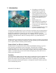
Total Online Kitchen™ Solution Package Coupled with E-Control Systems' enterprise Raptor Web Software™, equipment manufacturers, systems integrators, and IT professionals have a total Online Kitchen™ system to help manage a fully integrated restaurant. Never before has there been such a synergy between all aspects of the restaurant.
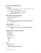
II. Features and Specifications Architecture CPU: Advanced High Performance Motorola 32-bit embedded PowerPC™ Network Processor with 66 MIPS at 50 MHz Memory: 16 Mbytes of SDRAM (expandable to 64 Mbytes) 2 Mbytes of Flash (expandable to 16 Mbytes) 512 Kbytes of battery-backed SRAM (optional) Real time clock with battery backup Serial Interface Port #1 and Port #2 Interface Type: CMOS, RS232, or RS485 Data Rates: 300 to 115.
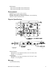
With Modem: Input Current (25 MHz Clock): 490mA max Input Current (50 MHz Clock): 610mA max Environmental Operating: 0 C to 70 C (32 F to 158 F) Storage: -40 C to 85 C (-40 F to 185 F) Humidity: Maximum 95% Relative Humidity, non-condensing Altitude: 10,000 ft (3048 m) max Physical Specifications TOLERANCES .010 Inches 4701000A1 Figure 1 Without Modem: Dimensions: 4.75x3.00x0.80 inches (120.7x76.2x20.4 mm) Weight: 3.1 oz (88 grams) With Modem: Dimensions: 4.75x3.00x1.09 inches (120.7x76.2x27.
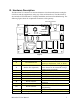
III. Hardware Description The MicroGate™ is meant to be connected between a local network/internet (using the LAN Port) and the equipment(s) (using any of the serial interfaces). The MicroGate™ also includes 4 LED indicators to simplify installation and network troubleshooting.
LED Indicators Table 2 - LED Indicators Name Condition Designator DS1 Link (green) DS2 Activity (green) DS3 Heartbeat (green) DS4 Power (green) Status The Ethernet Port has established a On valid network connection Network connection does Off not exist, or bad cable.
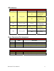
RS232 Serial Port Pin Assignment Table 5 - J4 (RS232 Channel #1) or J9 (Channel #2) Pin Number 1 2 3 4 5 6 7 8 9 Name Description Type CD DSR RX RTS TX CTS DTR RI Ground Input Input Input Output Output Input Output Input Power 10 +5V Carrier Detect Data Set Ready Receive Request To Send Transmit Clear To Send Data Terminal Ready Ring Indicator Ground Supply voltage, Must be regulated if power to board is being supplied from this pin (Option must be specified when ordering) Input RS485 Serial Port
Table 7 - J7 RS485 Channel #2 Pin Number Name 2 RS485_RX+ 4 RS485_RX- 6 RS485_GND RS485_TX+ 8 RS485_TX/RX+ RS485_TX10 RS485_TX/RX- MicroGate™ User Manual Description Non-Inverting Receiver Input (Full Duplex Mode) Inverting Receiver Input (Full Duplex Mode) RS485 Ground (Not signal Ground!!!) Non-Inverting Driver Output (Full Duplex mode) Non-Inverting Receiver Input / Driver Output (Half Duplex mode) Inverting Driver Output (Full Duplex mode) Inverting Receiver Input / Driver Output (Half Duplex
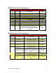
Ethernet (RJ45) Cable Specifications and Pin Assignments Figure 3 Cable 10BASE-T Table 8 - Cable Specification Type Max. Length Cat. 3, 4, 5 100-ohm UTP 100 m (328 ft) Connector RJ45 Table 9 - J1 Ethernet Pin MDI Signal Name Number 1 Transmit Data (TD+) 2 Transmit Data (TD-) 3 Receive Data (RD+) 6 Receive Data (RD-) Pins 4, 5, 7, and 8 are not connected.
IV. Installation and Configuration System Requirements You must meet the following requirements to install and configure the MicroGate™: • Static IP address, Subnet Mask, and Gateway Address to assign the MicroGate™ • A computer equipped with a 10 Mbps, 100 Mbps, or 10/100 Mbps Fast Ethernet Card, or USB-to-Ethernet converter. Computer must have TCP/IP protocols installed and have a fixed (static) or dynamic IP Address assigned to it.
Basic Network Configuration Procedure 1. Start the Discovery Utility by selecting Start > Programs > Raptor Web Software > ECSDiscovery – This utility might reside in a different location depending on how it was installed. Figure 4 2. Click on Start Discovery (see Figure 4, note #1) to start looking for E-Control Systems’ units on your network. Note: This could take up to 30 seconds to complete Figure 5 3.
Figure 6 4.
5. Change the IP Address, Subnet Mask, and Gateway Address as needed and then click on Update (see Figure 7, note #1) to send configuration to the unit. To quit without updating the unit, click on the X (see Figure 7, note #2) 6. Writing the configuration and restarting the unit can take as long as 2 minutes. In that time you will see DS3 stop flashing. When it starts flashing again you are done configuring the MicroGate™.
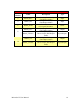
V. Part Number Selection See Figure 8 for configuration options and suggestions. For custom configurations please consult E-Control Systems. RS232 #1 RS232 #2 RS485 #1 and #2 Optional Special Build (Consult Factory) MG1- SL- XX- XX- XX-SPXXX Functional Options L No add-on modules M 33.
VI. Limited Warranties E-Control Systems' Limited Warranty Statement Limited Warranty Statement: E-Control Systems ("ECS") warrants its products to be free from defects in workmanship and materials, under normal use and service, for the applicable warranty term. All ECS products carry a standard 1 year limited warranty from the date of purchase from ECS or its Authorized Reseller/Distributors.
ADVISED OF THE POSSIBILITY OF SUCH DAMAGES. SOME COUNTRIES DO NOT ALLOW THE EXCLUSION OF IMPLIED WARRANTIES OR THE LIMITATION OF INCIDENTAL OR CONSEQUENTIAL DAMAGES FOR CONSUMER PRODUCTS, SO THE ABOVE LIMITATIONS AND EXCLUSIONS MAY NOT APPLY TO YOU. THIS WARRANTY GIVES YOU SPECIFIC LEGAL RIGHTS, WHICH MAY VARY FROM COUNTRY TO COUNTRY. NOTHING IN THIS WARRANTY SHALL BE TAKEN TO AFFECT YOUR STATUTORY RIGHTS. Firmware and Drivers For latest driver, technical information and bug-fixes please visit www.