HARDWARE REFERENCE Gateway Notebook
Contents Chapter 1: About this reference. . . . . . . . . . . . . . . . . . . . . . . . . . . . . . . . . . . . . . . . . . . . . . .1 About this guide . . . . . . . . . . . . . . . . . . . . . . . . . . . . . . . . . . . . . . . . . . . . . . . . . . . . . . . . Accessing the online User Guide . . . . . . . . . . . . . . . . . . . . . . . . . . . . . . . . . . . . . . . . . Gateway contact information . . . . . . . . . . . . . . . . . . . . . . . . . . . . . . . . . . . . . . . . . . . .
Contents www.gateway.com Chapter 3: Maintaining and Upgrading Your Notebook . . . . . . . . . . . . . . . . . . . . . . .31 Preventing static electricity discharge . . . . . . . . . . . . . . . . . . . . . . . . . . . . . . . . . . .32 Adding or replacing memory . . . . . . . . . . . . . . . . . . . . . . . . . . . . . . . . . . . . . . . . . . . .32 Replacing the DVD drive . . . . . . . . . . . . . . . . . . . . . . . . . . . . . . . . . . . . . . . . . . . . . . . .35 Replacing the hard drive kit . . .
CHAPTER 1 About this reference • About this guide • Accessing the online User Guide • Gateway contact information • Microsoft Certificate of Authenticity 1
CHAPTER 1: About this reference www.gateway.com About this guide This guide includes information and maintenance instructions that are specific to your model of Gateway notebook. For all other notebook information, see your online User Guide. Accessing the online User Guide In addition to this guide, the online User Guide has been included on your hard drive.
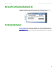
www.gateway.com Microsoft Certificate of Authenticity Microsoft Certificate of Authenticity The Microsoft Certificate of Authenticity label found on the bottom of your notebook includes the product key code for your operating system. For more information For more information about your notebook, visit Gateway’s Support page at support.gateway.com or the Web address shown on your notebook’s label. The Support page also has links to additional Gateway documentation and detailed specifications.
CHAPTER 1: About this reference 4 www.gateway.
CHAPTER 2 Checking Out Your Gateway Notebook • Identifying features • Connecting the AC adapter • Connecting the dial-up modem • Connecting to a cable or DSL modem or to an Ethernet network • Starting your notebook • Turning off your notebook • Restarting (rebooting) your notebook • Using the status indicators • Using the keyboard • Using the EZ Pad touchpad • Adjusting the volume • Turning your wireless radio on or off • Using the DVD drive • Using the memory card reader • Adding and removing a PC Card • C
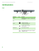
CHAPTER 2: Checking Out Your Gateway Notebook www.gateway.com Identifying features Front Speaker Component LCD panel release latch Headphone jack Battery Microphone jack charge indicator Power indicator Icon Description Speakers Provide audio output when headphones or amplified speakers are not plugged in. LCD panel release latch Slide to open the LCD panel. Battery charge indicator ■ ■ ■ ■ Power indicator ■ ■ ■ 6 Speaker LED blue - battery is fully charged.
www.gateway.com Identifying features Left Kensington lock slot S-Video out jack Component Icon Ventilation fan DVD drive Description Kensington™ lock slot Secure your notebook to an object by connecting a Kensington cable lock to this slot. S-Video out jack (optional) Plug an S-Video device, such as a television, into this optional jack. For more information, see Viewing the display on a television in the online User Guide. Ventilation fan Helps cool internal components.
CHAPTER 2: Checking Out Your Gateway Notebook www.gateway.com Right Memory card reader IEEE 1394 port PC Card slot USB ports Ethernet jack USB ports Modem jack Component 8 Icon Description PC Card slot Insert one Type II PC Card into this slot. For more information, see “Adding and removing a PC Card” on page 26. IEEE 1394 port Plug an IEEE 1394 (also known as Firewire® or i.Link®) device (such as a digital camcorder) into this 4-pin IEEE 1394 port.
www.gateway.com Identifying features Back Power connector Component Monitor port Icon Description Power connector Plug the AC adapter cable into this connector. Monitor port Plug an analog VGA monitor or projector into this port. For more information, see “Viewing the display on a projector or monitor” in the online User Guide.
CHAPTER 2: Checking Out Your Gateway Notebook www.gateway.com Bottom Battery latch Battery Memory bay Battery lock System label Hard drive bay Component 10 Icon Description Battery latch Slide to release the battery. For more information, see “Changing batteries” on page 27. Battery Provides power when your notebook is not plugged into AC power. Memory bay Install a memory module into this bay. For more information, see “Adding or replacing memory” on page 32.
www.gateway.com Identifying features Keyboard area Power button Keyboard Status indicators Component Icon Touchpad Description Power button Press to turn the power on or off. You can also configure the power button for Standby/Resume mode. For more information on configuring the power button mode, see “Changing Power-Saving Settings” in the online User Guide. Keyboard Provides all the features of a full-sized, computer keyboard. For more information, see “Using the keyboard” on page 18.
CHAPTER 2: Checking Out Your Gateway Notebook www.gateway.com Connecting the AC adapter Warning Do not attempt to disassemble the AC adapter. The AC adapter has no user-replaceable or user-serviceable parts inside. The AC adapter has dangerous voltages that can cause serious injury or death. Contact Gateway about returning defective AC adapters. Caution You can run your notebook using an AC adapter or your notebook’s battery. The battery was shipped to you partially charged.
www.gateway.com Connecting the dial-up modem 4 When you finish using your notebook for the first time, turn off your notebook and leave your notebook connected to AC power until the battery charge indicator turns blue. Protecting from power source problems Warning High voltages can enter your notebook through both the power cord and the modem connection. To protect your notebook and avoid electrical shock, use a surge protector. If you have a telephone modem, use a surge protector that has a modem jack.
CHAPTER 2: Checking Out Your Gateway Notebook www.gateway.com Connecting to a cable or DSL modem or to an Ethernet network Your notebook has a network jack that you can use to connect to a cable or DSL modem or to an Ethernet network. To connect to a cable or DSL modem or to an Ethernet network: 1 Insert one end of the network cable into the network jack on the right side of your notebook. 2 Insert the other end of the network cable into a cable modem, DSL modem, or Ethernet network jack.
www.gateway.com Starting your notebook Starting your notebook Warning Do not work for long periods with your notebook resting on your lap. If the air vents are blocked, your notebook may become hot enough to harm your skin. To start your notebook: 1 Slide the latch on the front of your notebook, then lift the LCD panel. 2 Press the power button located above the keyboard. Caution Provide adequate space around your notebook so air vents are not obstructed.
CHAPTER 2: Checking Out Your Gateway Notebook www.gateway.com Restarting (rebooting) your notebook Important If your notebook does not turn off immediately, complete the following steps until your notebook turns off: 1. Press and hold the power button for about five seconds, then release it. 2. Unplug the power cord and remove the battery for more than 10 seconds. If your notebook does not respond to keyboard, touchpad, or mouse input, you may have to close programs that are not responding.
www.gateway.com Using the status indicators Using the status indicators Important If none of the indicators are on, you may need to press FN+F1 to toggle the status indicators on. Status indicators inform you when a drive is being used or when a button has been pressed that affects how the keyboard is used. The status indicators are located below the touchpad.
CHAPTER 2: Checking Out Your Gateway Notebook www.gateway.com Using the keyboard Tips & Tricks You can attach an external keyboard to your notebook using a USB port. You do not need to shut down your notebook to connect a USB keyboard. Your notebook features a full-size keyboard that functions the same as a desktop computer keyboard.
www.gateway.com Using the keyboard Key type Icon Description FN key Press the FN key in combination with a colored system key to perform a specific action. Numeric keypad Use these keys to type numbers when the numeric keypad is turned on. Press FN+ 1 to turn on the numeric keypad. System key combinations When you press the FN key and a system key at the same time, your notebook performs the action identified by the text or icon on the key. Press and hold FN, then press this system key... To...
CHAPTER 2: Checking Out Your Gateway Notebook www.gateway.com Press and hold FN, then press this system key... F8 -+ To... Increase the LCD panel brightness above the normal brightest setting. Use this feature in bright lighting situations, such as outside in bright sunlight. Press a second time to decrease the brightness below the normal lowest brightness setting. Use this feature in dim lighting situations. Press a third time to return the display to the normal brightness setting.
www.gateway.com Using the EZ Pad touchpad Using the EZ Pad touchpad Tips & Tricks The EZ Pad™ consists of a touchpad, two buttons, and a scroll zone. For instructions on how to adjust the double-click speed, pointer speed, right-hand or left-hand configuration, and other touchpad settings, see “Changing the mouse or touchpad settings” in the online User Guide.
CHAPTER 2: Checking Out Your Gateway Notebook To... www.gateway.com Do this... Select an object on the screen. Position the pointer over the object. Quickly press and release the left button once. This action is called clicking. Start a program or open a file or folder. Position the pointer over the object. Press the left button twice in rapid succession. This action is called double-clicking. Access a shortcut menu or find more information about an object on the screen.
www.gateway.com Turning your wireless radio on or off Turning your wireless radio on or off Warning Radio frequency wireless communication can interfere with equipment on commercial aircraft. Current aviation regulations require wireless devices to be turned off while traveling in an airplane. IEEE 802.11a, IEEE 802.11b, IEEE 802.11g, and Bluetooth communication devices are examples of devices that provide wireless communication.
CHAPTER 2: Checking Out Your Gateway Notebook www.gateway.com Using the DVD drive You can use your notebook to enjoy a wide variety of multimedia features. Identifying drive types Your Gateway notebook may contain one of the following drive types. Look on the front of the drive for one or more of the following logos: If your drive has this logo... ROM/R/RW 24 This is your drive type... Use your drive for... DVD drive Installing programs, playing audio CDs, playing DVDs, and accessing data.
www.gateway.com Using the memory card reader Inserting a CD or DVD [ Eject button Manual eject hole To insert a CD or DVD: 1 Press the eject button on the DVD drive. After the tray opens slightly, pull the disc tray completely open. Important When you place a single-sided disc in the tray, make sure that the label side is facing up. If the disc has two playable sides, place the disc so the name of the side you want to play is facing up.
CHAPTER 2: Checking Out Your Gateway Notebook www.gateway.com Using a memory card To access a file on a memory card: 1 Click Start, then click My Computer. 2 Double-click the drive letter (for example, the E: drive), then double-click the file name. Removing a memory card To remove a memory card: Important Do not use the remove hardware icon in the taskbar to remove the memory card.
www.gateway.com Changing batteries To remove a PC Card: 1 Click the remove hardware Important If the remove hardware icon does not appear on the taskbar, click the show hidden icons button. icon in the taskbar, the PC Card name, then click Stop. -ORTurn off your notebook. 2 Release the eject button by pressing the PC Card eject button once. 3 Eject the PC Card by pressing the eject button again. Changing batteries Warning Danger of explosion if battery is incorrectly replaced.
CHAPTER 2: Checking Out Your Gateway Notebook www.gateway.com 4 Slide the battery lock to the unlocked position. 5 Slide the battery release latch, then slide the battery out of your notebook. 6 Slide a recharged battery into your notebook until it snaps into place. 7 Slide the battery lock to the locked position. 8 Turn your notebook over. 9 Open the LCD panel.
www.gateway.com Recalibrating the battery Recalibrating the battery Important Do not interrupt the battery recalibration process. If recalibration is interrupted, you must start the process over again. If your notebook unexpectedly goes into Standby mode while you are using it but the battery charge is not low, you may need to recalibrate your battery. You should also recalibrate the battery periodically to maintain the accuracy of the battery gauge.
CHAPTER 2: Checking Out Your Gateway Notebook www.gateway.com Printers You can attach almost any type of printer to your notebook. The most common types are inkjet and laser printers, which print in color or black and white. Inkjet printers and cartridges are relatively inexpensive, but they are slower than laser printers. Using an inkjet color printer, you can print pictures, banners, and greeting cards, as well as documents.
CHAPTER 3 Maintaining and Upgrading Your Notebook • Preventing static electricity discharge • Adding or replacing memory • Replacing the DVD drive • Replacing the hard drive kit • Replacing the keyboard 31
CHAPTER 3: Maintaining and Upgrading Your Notebook www.gateway.com Preventing static electricity discharge Warning To avoid exposure to dangerous electrical voltages and moving parts, turn off your notebook and unplug the power cord, modem cable, and network cable before opening the case. The components inside your notebook are extremely sensitive to static electricity, also known as electrostatic discharge (ESD).
www.gateway.com Adding or replacing memory 4 Disconnect all peripheral devices and remove any PC cards. 5 Turn your notebook over so the bottom is facing up, then remove the battery. For more information, see “Changing batteries” on page 27. Tips & Tricks The keyboard screw hole is marked with a K. Depending on your model, not all screws may be captive. 6 Remove the keyboard screw shown in the following picture, then loosen the remaining six captive screws (these screws cannot be removed).
CHAPTER 3: Maintaining and Upgrading Your Notebook www.gateway.com 8 If you are removing a module, gently press outward on the clip at each end of the memory module until the module tilts upward. 9 Pull the memory module out of the slot.
www.gateway.com Replacing the DVD drive Important 10 Hold the new or replacement module at a 30-degree angle and slide it into Use only memory modules designed for your Gateway notebook. the empty memory slot. This module is keyed so it can only be inserted in one direction. If the module does not fit, make sure that the notch in the module lines up with the tab in the memory bay. 11 Gently push the module down until it clicks in place. 12 Replace the memory bay cover, then tighten the captive screws.
CHAPTER 3: Maintaining and Upgrading Your Notebook Tips & Tricks The keyboard screw hole is marked with a K. Depending on your model, not all screws may be captive. www.gateway.com 7 Remove the keyboard screw shown in the following picture, then loosen the remaining six captive screws (these screws cannot be removed). Screw Screw Screw Screw Keyboard screw Screw Screw 8 Use the thumb notch to lift the memory bay cover, then remove it.
www.gateway.com Replacing the DVD drive 11 Insert a straightened paper clip into the DVD drive’s manual eject hole, push in the paper clip to eject the drive tray, then pull the drive tray open. 12 Carefully slide the drive out of the drive bay. 13 Slide the new DVD drive into the drive bay. Make sure that the drive fits securely in the bay. 14 Turn your notebook over so the bottom is facing up. 15 Secure the DVD drive with the screw removed in Step 9.
CHAPTER 3: Maintaining and Upgrading Your Notebook www.gateway.com Replacing the hard drive kit Tools Required You need a small Phillips screwdriver to replace the hard drive kit. You also need the operating system disc that came with your notebook. If you would like more hard drive capacity, you can replace your original drive with a higher-capacity drive.
www.gateway.com Replacing the hard drive kit 9 Remove the two hard drive bay cover screws, slide the hard drive bay cover, then remove it. The hard drive is attached to the back of the cover. 10 If your new hard drive already includes the hard drive cover, go to Step 15. -ORIf you need to move the hard drive cover from your old hard drive to your new hard drive, go to Step 11. 11 Remove the screws that secure the hard drive to the hard drive cover.
CHAPTER 3: Maintaining and Upgrading Your Notebook www.gateway.com 12 Remove the cover from the old drive. 13 Insert the new drive label side up onto the cover so the screw holes line up. 14 Replace the screws that secure the cover to the drive. 15 Slide the new hard drive kit into your notebook, then replace the cover screws. 16 Insert the battery, then turn your notebook over. 17 Connect the power adapter, modem cable, and network cable, then turn on your notebook.
www.gateway.com Replacing the keyboard 5 Turn your notebook over so the bottom is facing up, then remove the battery. For more information, see “Changing batteries” on page 27. Tips & Tricks 6 Remove the keyboard screw and put it in a safe place. The screw hole is marked with a K. Keyboard screw 7 Turn your notebook over so the top is facing up. 8 With a small Phillips screwdriver, remove the two hinge cover screws and put them in a safe place.
CHAPTER 3: Maintaining and Upgrading Your Notebook Important Inserting a piece of cloth between the screwdriver and keyboard will help prevent damage to your notebook. www.gateway.com 11 Insert the small flat-blade screwdriver under the right end of the keyboard cover and gently pry it up. 12 Pull the cover off your notebook. Be careful to not damage the LCD panel. 13 Gently lift the back edge of the keyboard. ■ ■ 42 If the keyboard does not lift, go to Step 14. If the keyboard lifts, go to Step 19.
www.gateway.com Replacing the keyboard Tips & Tricks Depending on your model, not all screws may be captive. 14 Close the LCD panel, turn your notebook over so the bottom is facing up, then loosen the six memory bay cover screws (these screws cannot be removed). Screw Screw Screw Screw Screw Screw 15 Use the thumb notch to lift the memory bay cover, then remove it. Be careful not to break off the tabs located on the end of the cover opposite of the thumb notch.
CHAPTER 3: Maintaining and Upgrading Your Notebook Important www.gateway.com 17 Remove the two optional keyboard screws. Depending on the keyboard features, one of both of these screws may be absent. Screw Screw 18 Turn your notebook over so the top is facing up, then open the LCD panel to the fully opened position. 19 With the back edge of the keyboard raised, carefully push it toward the LCD panel to release the keyboard retaining tabs. Be careful not to damage the LCD panel.
www.gateway.com Replacing the keyboard 21 Slide the black keyboard connector clip to the front of your notebook and remove the cable. Be careful not to touch or damage any other components. Keyboard connector clip Installing the keyboard To install the keyboard: 1 Place the new keyboard keys-down on your notebook with the space bar away from you. Important The keyboard cable is correctly oriented if it is not twisted.
CHAPTER 3: Maintaining and Upgrading Your Notebook www.gateway.com 4 Insert the tabs on the front edge of the keyboard into the slots under the palm rest. You may need to press down on the keyboard keys along the front edge of the keyboard to seat the retaining tabs into their corresponding slots. 5 Gently press the keyboard down until it is flat all the way across. The keyboard should easily fall into place. Be careful to not damage the LCD panel. Caution 6 Replace the keyboard cover.
APPENDIX A Safety, Regulatory, and Legal Information • Important safety information • Regulatory compliance statements • Environmental information • Notices 47
APPENDIX A: Safety, Regulatory, and Legal Information www.gateway.com Important safety information Warning Always follow these instructions to help guard against personal injury and damage to your Gateway system. Your Gateway notebook is designed and tested to meet the latest standards for safety of information technology equipment. However, to ensure safe use of this notebook, it is important that the safety instructions marked on your notebook and in the documentation are followed.
www.gateway.com ■ Unplug the notebook from the wall outlet and refer servicing to qualified personnel if: ■ The power cord or plug is damaged. ■ Liquid has been spilled into the notebook. ■ The notebook does not operate properly when the operating instructions are followed. ■ The notebook was dropped or the cabinet is damaged. ■ The notebook performance changes. Replacement parts and accessories Use only replacement parts and accessories recommended by Gateway.
APPENDIX A: Safety, Regulatory, and Legal Information www.gateway.com Regulatory compliance statements Wireless guidance Warning Radio frequency wireless communication can interfere with equipment on commercial aircraft. Current aviation regulations require wireless devices to be turned off while traveling in an airplane. 802.11b (also known as wireless Ethernet or Wifi) and Bluetooth communication devices are examples of devices that provide wireless communication.
www.gateway.com United States of America Caution Wireless devices are not user-serviceable. Do not modify them in any way. Modification to a wireless device will void the authorization to use it. Contact Gateway for service. Caution The transmitting device embedded in this notebook may not be used with any antenna other than the one provided with the notebook.
APPENDIX A: Safety, Regulatory, and Legal Information Caution Changes or modifications not expressly approved by Gateway could void the FCC compliance and negate your authority to operate the notebook. Caution Recycle or dispose of the used notebook properly according to federal, state and local laws. www.gateway.com FCC declaration of conformity Responsible party: Gateway Companies, Inc.
www.gateway.com This equipment cannot be used on telephone company-provided coin service. Connection to party line service is subject to state tariffs. Contact the state public utility commission or public service commission for information. When programming or making test calls to emergency numbers: ■ ■ Remain on the line and briefly explain to the dispatcher the reason for the call. Perform such activities in the off-peak hours such as early morning or late evenings.
APPENDIX A: Safety, Regulatory, and Legal Information www.gateway.com Telecommunications per Industry Canada CS-03 (for products fitted with an IC-compliant modem) The Industry Canada label identifies certified equipment. This certification means that the equipment meets certain telecommunications network protective, operation, and safety requirements. The Department does not guarantee the equipment will operate to the users’ satisfaction.
www.gateway.com Laser safety statement Warning Use of controls or adjustments or performance of procedures other than those specified in this manual may result in hazardous radiation exposure. To prevent exposure to laser beams, do not try to open the enclosure of a CD or DVD drive. All Gateway systems equipped with CD and DVD drives comply with the appropriate safety standards, including IEC 825.
APPENDIX A: Safety, Regulatory, and Legal Information www.gateway.com Environmental information The product you have purchased contains extracted natural resources that have been used in the manufacturing process. This product may contain substances known to be hazardous to the environment or to human health.
www.gateway.com Notices Copyright © 2006 Gateway, Inc. All Rights Reserved 7565 Irvine Center Drive Irvine, CA 92618 USA All Rights Reserved This publication is protected by copyright and all rights are reserved. No part of it may be reproduced or transmitted by any means or in any form, without prior consent in writing from Gateway. The information in this manual has been carefully checked and is believed to be accurate. However, changes are made periodically.
APPENDIX A: Safety, Regulatory, and Legal Information 58 www.gateway.
Index A AC adapter connecting 12 connector 9 accessories purchasing 29 safety precautions 49 application key 18 arrow keys 18 audio adjusting volume 20 back button 20 headphone jack 6 microphone jack 6 muting 20, 22 next button 20 pause button 20 play button 20 stop button 20 volume down button 20 volume up button 20 B battery bay 27 changing 27 charge indicator 6 charging 12 installing 27 latch 10 locating 10 purchasing 29 recalibrating 29 recharging 12 release latch 10 replacing 27 bays battery 27 hard d
Index www.gateway.
www.gateway.
Index 62 www.gateway.
MAN BLADE E/K8/C HW REF R1 2/06