Gateway Profile™ 4 service guide Customizing Troubleshooting
Contents Replacing Components in Your Gateway Profile 4 . . . . . . . . . . . . . . . 1 About this guide . . . . . . . . . . . . . . . . . . . . . . . . . . . . . . . . . . . . . . . . . . . . . . . . . . . . . 1 Preparing your work space . . . . . . . . . . . . . . . . . . . . . . . . . . . . . . . . . . . . . . . . . . . . 2 Preventing static electricity discharge . . . . . . . . . . . . . . . . . . . . . . . . . . . . . . . . . . . . 3 Preparing your computer . . . . . . . . . . . . . . . . . . . . . . .
ii
Replacing Components in Your Gateway Profile 4 About this guide Use this service guide to help plan your maintenance tasks for the Gateway Profile 4. All tasks covered in this guide can be performed by a field technician without jeopardizing your computer’s warranty. For information on your computer’s general maintenance, technical support, safety notices, and regulatory notices, see your Gateway user’s guide.
Thank you for purchasing this Factory Service Manual CD/DVD from servicemanuals4u.com.
Replacing Components in Your Gateway Profile 4 Preparing your work space Before performing maintenance on your computer, make sure that your work space and your computer are correctly prepared. 2 ■ Wear a grounding (ESD) wrist strap. ■ Use a grounded or dissipative work mat. ■ Use a stable and strong table. ■ Make sure that the table top is large enough to hold each component as you remove it. ■ Use bright lighting to make part identification easier.
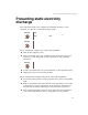
Preventing static electricity discharge Preventing static electricity discharge The components inside your computer are extremely sensitive to static electricity, also known as electrostatic discharge (ESD). Warning ESD can permanently damage electrostatic discharge-sensitive components in your computer. Prevent ESD damage by following ESD guidelines every time you open the computer case.
Replacing Components in Your Gateway Profile 4 Preparing your computer Warning To avoid exposure to dangerous electrical voltages and moving parts, turn off your computer, then unplug the power cord before opening the case. To prepare your computer: 1 2 Turn off your computer. 3 Press the power button to drain any residual power from your computer. Following all static electricity discharge precautions, disconnect the power cord and all other external cables.
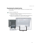
Replacing drives Replacing the diskette drive The removable drive pack contains the diskette drive, drive adapter card, and an optical drive. To replace the diskette drive: 1 Turn off the computer and prepare it by following the instructions in “Preparing your computer” on page 4. 2 Remove the two retaining screws located on either side of the Microsoft Certificate of Authenticity label on the back of your computer. Screws www.gateway.
Replacing Components in Your Gateway Profile 4 6 3 Slide the drive pack forward, then down. 4 Disconnect the two drive cables from the drive adapter card. Note the location and orientation of each cable. You will reconnect these cables later. www.gateway.
Replacing drives 5 Disconnect the diskette drive cable from the ZIF connector on the drive adapter card. www.gateway.
Replacing Components in Your Gateway Profile 4 6 Remove the four screws that secure the diskette drive to the drive pack. Screws Screws 8 www.gateway.
Replacing drives 7 Remove the old diskette drive. 8 Insert the new diskette drive and secure it with the four screws removed in Step 6. www.gateway.
Replacing Components in Your Gateway Profile 4 10 9 Connect the diskette drive cable, making sure that it is fully seated in the ZIF connector. 10 Connect the drive cables to the drive adapter card on the drive pack using the notes you made in Step 4. The drive cables and connectors are “keyed,” which means that they can only be plugged in one way. 11 Push the cables carefully up into the top of the drive bay. www.gateway.
Replacing drives 12 Align the tabs on the drive pack with the notches on the drive bay, then slide the drive pack back until it is flush with the front of the case. Tabs 13 Secure the drive pack with the two screws removed in Step 2. www.gateway.
Replacing Components in Your Gateway Profile 4 Replacing the optical drive The removable drive pack contains the diskette drive, drive adapter card, and an optical drive. The optical drive may be a CD, DVD, or recordable drive. To replace the optical drive: 1 Turn off the computer and prepare it by following the instructions in “Preparing your computer” on page 4. 2 Remove the two retaining screws located on either side of the Microsoft Certificate of Authenticity label on the back of your computer.
Replacing drives 3 Slide the drive pack forward, then down. 4 Disconnect the two drive cables from the drive adapter card. Note the location and orientation of each cable. You will reconnect these cables later. www.gateway.
Replacing Components in Your Gateway Profile 4 5 Remove the four screws that secure the optical drive to the drive pack. Left Side Screw Screw Right Side Screw 14 Screw www.gateway.
Replacing drives 6 Slide the optical drive out of the drive pack. 7 Slide in the new optical drive and secure it with the four screws removed in Step 5. 8 Connect the drive cables to the drive adapter card on the drive pack using the notes you made in Step 4. The drive cables and connectors are “keyed,” which means that they can only be plugged in one way. www.gateway.
Replacing Components in Your Gateway Profile 4 9 10 Push the cables carefully up into the top of the drive bay. Align the tabs on the drive pack with the notches on the drive bay, then slide the drive pack back until it is flush with the front of the case. Tabs 11 16 Secure the drive pack with the two screws removed in Step 2. www.gateway.
Replacing drives Replacing the hard drive Use this procedure to replace the hard drive. Tips & Tricks For more stability, place your computer face down to perform this procedure. Avoid scratching the computer display by placing it on a towel or other non-abrasive surface. To replace the hard drive: 1 Turn off the computer and prepare it by following the instructions in “Preparing your computer” on page 4. 2 Remove the two screws that secure the access panel to the back of the computer case.
Replacing Components in Your Gateway Profile 4 18 3 With your hands positioned on each side of the case, swing the access panel up and away from the case and set the access panel aside. 4 Unsnap the two hard drive cage tabs. 5 Remove the hard drive cage from your computer. www.gateway.
Replacing drives 6 Disconnect the drive cable and power cable. Note the location and orientation of each cable. You will reconnect these cables later. www.gateway.
Replacing Components in Your Gateway Profile 4 7 Remove the four screws that secure the drive to the hard drive cage. Screws Screws 8 20 Remove the drive. www.gateway.
Replacing drives 9 Make sure that the jumpers on the new drive are set the same as the jumpers on the drive you are replacing. Jumpers 10 Insert the new drive into the hard drive cage and secure it with the four screws removed in Step 7. 11 Connect the drive cable and power cable to the drive using the notes you made in Step 6. 12 Align the single hard drive cage tab into the case notch, then swing the hard drive cage down until the two hard drive cage tabs on the other side snap into place. www.
Replacing Components in Your Gateway Profile 4 13 Make sure that all of the internal cables are arranged inside the case so they will not be pinched when you close the case. 14 Align the access panel tabs into the case notches. Access panel tabs 15 22 Swing the access panel down into place and secure it with the two screws removed in Step 2. www.gateway.
Replacing the Mini PCI card Replacing the Mini PCI card If you need to install a new Mini PCI card, you must first remove the existing card. Warning Replace the Mini PCI card with only Gateway-approved cards. Tools you need to complete this task: Phillips screwdriver Tips & Tricks For more stability, place your computer face down to perform this procedure. Avoid scratching the computer display by placing it on a towel or other non-abrasive surface. www.gateway.
Replacing Components in Your Gateway Profile 4 To replace the Mini PCI card: 1 Turn off the computer and prepare it by following the instructions in “Preparing your computer” on page 4. 2 Remove the two screws that secure the access panel to the back of the computer case. Screws 24 www.gateway.
Replacing the Mini PCI card 3 With your hands positioned on each side of the case, swing the access panel up and away from the case and set the access panel aside. 4 Unsnap the two hard drive cage tabs. www.gateway.
Replacing Components in Your Gateway Profile 4 5 6 26 Remove the hard drive cage from your computer. Disconnect the drive cable and power cable and set the drive cage aside. Note the location and orientation of each cable. You will reconnect these cables later. www.gateway.
Replacing the Mini PCI card 7 Remove the tape that secures the antenna cables to the Mini PCI wireless network card. (Shown with back case cover off, for clarity.) 8 Disconnect the antenna cables from the network card. www.gateway.
Replacing Components in Your Gateway Profile 4 9 10 28 Press outward on both of the retaining clips holding the network card until the card tips up at an angle. Remove the network card. www.gateway.
Replacing the Mini PCI card 11 Carefully press the new network card into the card slot. The network card must be fully seated in the slot before the retaining clips will snap into place. 12 Plug the antenna cables back into the network card. The white wire connects to the post labeled MAIN, and the black wire connects to the post labeled AUX. 13 Secure the wires to the network card by reapplying the tape you removed in Step 7.
Replacing Components in Your Gateway Profile 4 30 15 Align the single hard drive cage tab into the case notch, then swing the hard drive cage down until the two hard drive cage tabs on the other side snap into place. 16 Make sure that all of the internal cables are arranged inside the case so they will not be pinched when you close the case. www.gateway.
Replacing the Mini PCI card 17 Align the access panel tabs into the case notches. Access panel tabs 18 Swing the access panel down into place and secure it with the two screws removed in Step 2. www.gateway.
Replacing Components in Your Gateway Profile 4 Installing or replacing DIMM memory Important Use only DDR266 DIMM memory. Tools you need to complete this task: Phillips screwdriver Tips & Tricks 32 For more stability, place your computer face down to perform this procedure. Avoid scratching the computer display by placing it on a towel or other non-abrasive surface. www.gateway.
Installing or replacing DIMM memory To install or replace DIMM memory: 1 Turn off the computer and prepare it by following the instructions in “Preparing your computer” on page 4. 2 Remove the two screws that secure the access panel to the back of the computer case. Screws www.gateway.
Replacing Components in Your Gateway Profile 4 3 With your hands positioned on each side of the case, swing the access panel up and away from the case and set the access panel aside. 4 Find the memory module banks, sometimes called add-in slots, on your system board. Memory modules 34 www.gateway.
Installing or replacing DIMM memory 5 If you are removing a memory module from the memory module bank, gently pull the plastic tabs away from the sides of the memory module and remove it. - OR If you are adding a memory module to an empty memory module bank, gently pull the plastic tabs away from the sides of the memory module bank. 6 Align the notch on the new memory module with the notch on the memory module bank and press firmly into the bank.
Replacing Components in Your Gateway Profile 4 8 Align the access panel tabs into the case notches. Access panel tabs 9 10 11 12 Swing the access panel down into place and secure it with the two screws removed in Step 2. Reconnect the external cables and power cord. Turn on your computer. Windows starts and the Windows desktop appears. In Windows XP, click Start, Control Panel, then click Performance and Maintenance (if in Category View). Click/Double-click System.
Replacing the fan Replacing the fan Tools you need to complete this task: Phillips screwdriver Tips & Tricks For more stability, place your computer face down to perform this procedure. Avoid scratching the computer display by placing it on a towel or other non-abrasive surface. www.gateway.
Replacing Components in Your Gateway Profile 4 To replace the fan: 1 Turn off the computer and prepare it by following the instructions in “Preparing your computer” on page 4. 2 Remove the two screws that secure the access panel to the back of the computer case. Screws 38 www.gateway.
Replacing the fan 3 With your hands positioned on each side of the case, swing the access panel up and away from the case and set the access panel aside. 4 Remove the four screws that secure the fan to the heatsink. Screws Screws www.gateway.
Replacing Components in Your Gateway Profile 4 5 40 Disconnect the fan power cable. Note the location and orientation of the cable. You will reconnect this cable later. www.gateway.
Replacing the fan 6 Remove the old fan. 7 Secure the new fan to the heatsink with the four screws removed in Step 4. www.gateway.
Replacing Components in Your Gateway Profile 4 8 9 10 Connect the fan power cable using the notes you made in Step 5. Make sure that all of the internal cables are arranged inside the case so they will not be pinched when you close the case. Align the access panel tabs into the case notches. Access panel tabs 11 42 Swing the access panel down into place and secure it with the two screws removed in Step 2. www.gateway.
Replacing the LCD panel inverter board Replacing the LCD panel inverter board Tools you need to complete this task: Phillips screwdriver Flat-blade screwdriver To replace the LCD panel inverter board: 1 Turn off the computer and prepare it by following the instructions in “Preparing your computer” on page 4. 2 Lay the computer down on its back. www.gateway.
Replacing Components in Your Gateway Profile 4 3 Starting at the bottom center of the LCD panel bezel, carefully work your fingers under the plastic to pry the bezel away from the LCD panel. Work your fingers between the LCD glass and the bezel, not underneath the outside of the bezel. 4 Continue to work your fingers around each side of the screen while carefully prying the plastic tabs on the bezel away from the LCD panel.
Replacing the LCD panel inverter board 5 Remove the four screws that hold the LCD panel to the case. Warning Be careful while handling the LCD panel, and do not touch the LCD screen with any sharp object. Screws 6 Carefully tilt the bottom of the LCD panel slightly away from the case to access the cables behind the panel. www.gateway.
Replacing Components in Your Gateway Profile 4 7 Unplug the cable from the side of the inverter board closest to you (nearest the “open” side of the tilted LCD panel). 8 Tilt the LCD panel up further and unplug the other cable from the inverter board, then unplug the scaler board connector from the LCD panel. Scaler board Inverter board 9 46 Remove the LCD panel from the computer and set it aside. www.gateway.
Replacing the LCD panel inverter board 10 Unplug the cable that connects the inverter board to the scaler board, then remove the mounting screw on the inverter board. Screw www.gateway.
Replacing Components in Your Gateway Profile 4 11 Remove the inverter board from the computer. Tips & Tricks 12 Hold the new inverter board by its edges, then align the mounting holes with the standoffs and attach the screw to the new board. Warning 13 14 15 48 Mark or label the removed board as “defective” to prevent confusion with the new board. Do not press or apply pressure to the inverter board’s components or plastic shields. Place the LCD panel back onto the computer.
Replacing the LCD panel inverter board 16 On the side of the inverter board closest to the bottom of the LCD panel, connect: ■ The pink and white cable to the connector labeled CN2. ■ The blue and black cable to the connector labeled CN3. Warning The connectors should easily press into place. If you have difficulty attaching a connector, it may be turned upside-down. Turn the connector over and try again.
Replacing Components in Your Gateway Profile 4 20 50 Align the plastic bezel’s tabs with the tab slots on the computer, then firmly press the bezel into place. Make sure all four edges are correctly attached and that the bezel has a tight fit. www.gateway.
Replacing the system board Replacing the system board Tools you need to complete this task: Phillips screwdriver Flat-blade screwdriver To replace the system board: 1 Turn off the computer and prepare it by following the instructions in “Preparing your computer” on page 4. 2 Remove the two retaining screws located on either side of the Microsoft Certificate of Authenticity label on the back of your computer. Screws www.gateway.
Replacing Components in Your Gateway Profile 4 52 3 Slide the drive pack forward, then down. 4 Disconnect the two drive cables from the drive adapter card and set the drive pack aside. Note the location and orientation of each cable. You will reconnect these cables later. www.gateway.
Replacing the system board 5 Remove the two screws that secure the access panel to the back of the computer case. Screws 6 With your hands positioned on each side of the case, swing the access panel up and away from the case and set the access panel aside. www.gateway.
Replacing Components in Your Gateway Profile 4 54 7 Unsnap the two hard drive cage tabs. 8 Remove the hard drive cage from your computer. www.gateway.
Replacing the system board 9 Disconnect the drive cable and power cable. Note the location and orientation of each cable. You will reconnect these cables later. www.gateway.
Replacing Components in Your Gateway Profile 4 10 Press the PC Card eject button so the eject button is extended. PC Card eject button 56 11 Pull off the rubber eject button cover, then push the PC Card eject button back in so it is flush with the system case. 12 Remove the tape that secures the antenna cables to the network card. www.gateway.
Replacing the system board 13 Disconnect the antenna cables from the network card. 14 Disconnect the fan power cable. Note the location and orientation of the cable. You will reconnect this cable later. www.gateway.
Replacing Components in Your Gateway Profile 4 15 Remove the four heatsink screws. Screws Screws 58 www.gateway.
Replacing the system board 16 Gently move the heat sink side to side to make sure that the seal on the processor is loosened, then swing the heatsink up and away from the computer. www.gateway.
Replacing Components in Your Gateway Profile 4 17 Remove the six back case cover screws. Screws 18 60 Place your computer face down. Avoid scratching the computer display by placing it on a towel or other non-abrasive surface. www.gateway.
Replacing the system board 19 Use a flat-blade screwdriver to push out the four side screw caps from inside the case, then use the screwdriver to remove the screw caps (two on each side of the case). Screw caps www.gateway.
Replacing Components in Your Gateway Profile 4 20 Use a Philips screwdriver to remove the four case cover side screws (two on each side of the case). Screws 62 www.gateway.
Replacing the system board 21 Push up slightly on the stand so you can release the two case retaining tabs on the bottom of the computer. Bottom case retaining tabs 22 Press in on the case cover to release the case retaining tabs. www.gateway.
Replacing Components in Your Gateway Profile 4 23 64 Lift the case cover straight up, then set it aside. www.gateway.
Replacing the system board 24 Disconnect the hard drive, power, and LED cables from the system board. Disconnect the speaker and headphone/microphone jack cables from the audio card. Note the location and orientation of each cable. You will reconnect these cables later. Hard drive cable LED cable Power cable Headphone/Microphone jack cable Speaker cables www.gateway.
Replacing Components in Your Gateway Profile 4 25 Remove the five screws holding the hard drive suspension plate to the system board, then remove the plate. Hard drive suspension plate Screws 66 www.gateway.
Replacing the system board 26 Remove the two screws holding the card retention plate to the computer chassis, then remove the plate. Card retention plate Screws www.gateway.
Replacing Components in Your Gateway Profile 4 27 Remove the three screws securing the two gray card brackets to the system board. Screws Screw 28 29 68 Remove the two gray card brackets. Remove the three cards from the system board. Note each card’s location and orientation. You will reinstall these cards later. You can slightly seesaw a card end-to-end as you work it out of the slot, but do not bend the card sideways. www.gateway.
Replacing the system board 30 Disconnect the LCD video, LCD power, diskette drive, and optical drive cables from the system board. Note the location and orientation of each cable. You will reconnect these cables later. LCD video cable Optical drive cable LCD power cable Diskette drive cable www.gateway.
Replacing Components in Your Gateway Profile 4 31 Remove the five additional system board retaining screws. Screws Screws 70 www.gateway.
Replacing the system board 32 Lift the system board away from the computer. 33 Secure the new system board to the computer with the five screws removed in Step 31. www.gateway.
Replacing Components in Your Gateway Profile 4 34 Connect the LCD video, LCD power, diskette drive, and optical drive cables to the system board using the notes you made in Step 30. LCD video cable Optical drive cable LCD power cable Diskette drive cable 72 35 Secure the two card brackets to the system board with the three screws removed in Step 27. 36 Insert the three cards into the slots using the notes you made in Step 29.
Replacing the system board 38 Secure the hard drive suspension plate to the system board with the five screws removed in Step 25. 39 Connect the hard drive, power, and LED cables to the system board, then connect the speaker and headphone/microphone jack cable to the audio card using the notes you made in Step 24. Hard drive cable LED cable Power cable Headphone/Microphone jack cable Speaker cables www.gateway.
Replacing Components in Your Gateway Profile 4 40 Replace the case cover making sure that the case retaining tabs snap into place. 41 Replace the four side screws and screw caps removed in Step 19 and Step 20. 42 43 Replace the six back case cover screws removed in Step 17. 44 74 Plug the antenna cables back into the wireless network card. The white wire connects to the post labeled MAIN, and the black wire connects to the post labeled AUX.
Replacing the system board 45 Align the heatsink tab into the slot on the system board and swing the heatsink back into place, then secure the heatsink with the four screws removed in Step 15. 46 47 Connect the fan power cable. Connect the drive cable and power cable to the hard drive pack using the notes you made in Step 9. www.gateway.
Replacing Components in Your Gateway Profile 4 76 48 Align the single hard drive cage tab into the case notch, then swing the hard drive cage down until the two hard drive cage tabs on the other side snap into place. 49 Make sure that all of the internal cables are arranged inside the case so they will not be pinched when you close the case. 50 Replace the PC Card eject button cover. www.gateway.
Replacing the system board 51 Align the access panel tabs into the case notches. Access panel tabs 52 Swing the access panel down into place and secure it with the two screws removed in Step 5. 53 54 Return the computer to the upright position. 55 Push the cables carefully up into the top of the drive bay. Connect the drive cables to the drive adapter card on the drive pack using the notes you made in Step 4.
Replacing Components in Your Gateway Profile 4 56 Align the tabs on the drive pack with the notches on the drive bay, then slide the drive pack back until it is flush with the front of the case. Tabs 57 78 Secure the drive pack with the two screws removed in Step 2. www.gateway.
MAN US PFL4.