E-9520T Server USERGUIDE ®
Contents Chapter 1: Checking Out Your Gateway Server . . . . . . . . . . . . . . . . . . . . . . . 1 Front . . . . . . . . . . . . . . . . . . . . . . . . . . . . . . . . . . . . . . . . . . . . . . . . . . . . . . . . . . . . . . Back . . . . . . . . . . . . . . . . . . . . . . . . . . . . . . . . . . . . . . . . . . . . . . . . . . . . . . . . . . . . . . Connectors and LEDs . . . . . . . . . . . . . . . . . . . . . . . . . . . . . . . . . . . . . . . . . . Interior . . . . . . . . . . . . . . . . . . . .
Contents Opening the server case . . . . . . . . . . . . . . . . . . . . . . . . . . . . . . . . . . . . . . . . . . . . . Closing the server case . . . . . . . . . . . . . . . . . . . . . . . . . . . . . . . . . . . . . . . . . . . . . . Installing and removing drives . . . . . . . . . . . . . . . . . . . . . . . . . . . . . . . . . . . . . . . . Removing and installing an optical drive . . . . . . . . . . . . . . . . . . . . . . . . . Removing and installing a hard drive . . . . . . . . . . . . . . . . .
www.gateway.com Optical drive . . . . . . . . . . . . . . . . . . . . . . . . . . . . . . . . . . . . . . . . . . . . . . . . Expansion cards . . . . . . . . . . . . . . . . . . . . . . . . . . . . . . . . . . . . . . . . . . . . . Hard drive . . . . . . . . . . . . . . . . . . . . . . . . . . . . . . . . . . . . . . . . . . . . . . . . . . Internet . . . . . . . . . . . . . . . . . . . . . . . . . . . . . . . . . . . . . . . . . . . . . . . . . . . . Keyboard . . . . . . . . . . . . . . . . . . . . . . .
Contents iv
CHAPTER1 Checking Out Your Gateway Server • • • • • • Front Back Interior System board Hot-swap backplanes Getting Help 1
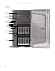
CHAPTER 1: Checking Out Your Gateway Server Front Optical drive SMIL connector Second optical drive (optional) NMI button System fault LED Reset button NIC status LED ID button ID LED Hard drive cages Power LED Power button Case cover lock Dual USB ports Diskette drive (optional) 2
www.gateway.
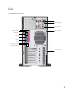
CHAPTER 1: Checking Out Your Gateway Server Interior Important Server components with green handles or retention locks can be hot swapped while the server is on. Server components with blue handles or retention locks can only be removed when the server is turned off. 4 # Feature # Feature 1 Power supply 5 Front panel 2 Power distribution board 6 Hard drive bays 3 System fans (hot swap) 7 SAS/SATA backplane 4 5.
www.gateway.
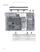
CHAPTER 1: Checking Out Your Gateway Server # Feature # Feature 10 D-sub VGA port (J24) 35 Server management connector (J34) 11 Serial port (J15) 36 COM2 connector (J60) 12 Dual USB connector (J12) 37 MFG connector (J48) 13 PS/2 keyboard and mouse ports (J10) 38 Onboard USB connector (J61) 14 System fan connector (J4) 39 IDE connector (J54) 15 System fan connector (J3) 40 Floppy connector (J49) 16 Main power connector (J7) 41 PCI-X mezzanine board connector (J44) 17 DIMM 1
www.gateway.
CHAPTER 1: Checking Out Your Gateway Server Getting Help In addition to your operating system’s documentation, you can use the following information resources to help you use your server. Server Companion DVD Use the Server Companion DVD to access file utilities, Windows Server 2003 drivers, and documentation for your server and its components. For instructions, see Using Your Server Companion DVD. Gateway Web site Gateway provides a variety of information on its Web site to help you use your server.
CHAPTER2 Setting Up Your Server • • • • • Setting up the hardware Protecting from power source problems Starting your server Setting up the operating system Initial hardware settings 9
CHAPTER 2: Setting Up Your Server Setting up the hardware To make sure that your working environment is safe: Caution Your server comes with a 3-wire AC power cord(s) fitted with the correct plug style for your region. If the plug(s) does not match the connector on your surge protector, UPS, or wall outlet, do not attempt to modify the plug(s) in any way. Use a surge protector, UPS, or wall outlet that is appropriate for the supplied AC power cord(s).
www.gateway.com Some surge protectors and uninterruptible power supplies include simple line-conditioning capabilities. Uninterruptible power supplies Use an uninterruptible power supply (UPS) to protect your server from data loss during a total power failure. A UPS uses a battery to keep your server running temporarily during a power failure and lets you save your work and shut down your server. You cannot run your server for an extended period of time while using only the UPS.
CHAPTER 2: Setting Up Your Server 6 Swing the bezel out 45° from the front of the case, then disengage the tabs on the right side of the bezel from the chassis and remove it. 7 To reinstall the bezel, align the right side of the bezel with the right side of the chassis at a 45° angle, then insert the three tabs on the right side of the bezel into the slots in the chassis. 8 Swing the left side of the bezel in to the chassis until the three tabs on the left side of the bezel snap into place.
www.gateway.com To start the server: 1 Turn on any peripheral devices connected to the server. 2 Press the power button. The power LED turns green. Power LED Power button If nothing happens when you press the power button: • Make sure that the power cable(s) is plugged in securely and that your surge protector • • (if you are using one) is plugged in and turned on. Make sure that the monitor is connected to the server, plugged into the power outlet or surge protector, and turned on.
CHAPTER 2: Setting Up Your Server Turning off your server Every time you turn off your server, first shut down the operating system. You may lose data if you do not follow the correct procedure. To turn off the server: Caution The power button on the server does not turn off server AC power. To remove AC power from the server, you must unplug the AC power cords from the wall outlet or power source. The power cords are considered the disconnect device to the main (AC) power.
CHAPTER3 Maintaining Your Server • • • • • Caring for your server Preparing for system recovery System administration Identifying your server Updating the baseboard management controller firmware • Using your Server Companion DVD 15
CHAPTER 3: Maintaining Your Server Caring for your server To extend the life of your server: • Be careful not to bump or drop your server. • When transporting your server, we recommend that you put it in the original packaging materials. • Keep your server and magnetic media away from equipment that generates magnetic fields, such as unshielded speakers. • Avoid subjecting your server to extreme temperatures. Do not expose your server to heating ducts or other heat-generating objects.
www.gateway.com Cleaning the screen Caution The computer screen is made of specially coated glass and can be scratched or damaged by abrasive or ammonia-based glass cleaners. If your computer screen is an LCD, use only a damp, soft cloth to clean it. Never spray water directly onto the screen. - OR If your computer screen is not an LCD, use a soft cloth dampened with glass cleaner to clean the screen. Never spray cleaner directly onto the screen.
CHAPTER 3: Maintaining Your Server Server security Locking the server To lock the server: 1 Remove the bezel lock keys from the inside of the bezel, then snap on the bezel. The handles must be installed for the bezel to snap on. For instructions, see “Removing and installing the bezel” on page 11. 2 Insert the key into the lock and rotate it ¼ turn clockwise. To unlock it, rotate the key ¼ turn counter-clockwise.
www.gateway.
CHAPTER 3: Maintaining Your Server To install Acrobat Reader 7: • Click the link for Acrobat on the Documentation page. - OR Run Docs\Reader\app21279\Setup.exe from the Server Companion DVD. Installing drivers and programs Important The Server Companion DVD’s Gateway Application and Driver Recovery utility works only in Windows operating systems. You can install drivers and programs directly onto the server by using the Server Companion DVD.
www.gateway.com 3 Press any key to boot from the DVD. The Gateway Options Main Menu appears. 4 Follow any on-screen instructions. You can use the options in this menu to reformat your hard drive, create mass-storage driver disks, or reload Windows and selected applications.
CHAPTER 3: Maintaining Your Server 22
CHAPTER4 Installing Components • • • • • • • • • • • • • Preparing to install components Preventing static electricity discharge Opening the server case Closing the server case Installing and removing drives Installing memory Installing and removing PCI expansion cards Replacing system fans Replacing or adding a processor Replacing a power supply module and power board Replacing the hot-swap backplanes Replacing the CMOS battery Replacing the system board 23
CHAPTER 4: Installing Components Preparing to install components Selecting a place to work Work on your server in an area that: • Is clean (avoid dusty areas). • Is a low-static environment (avoid carpeted areas). • Has a stable surface on which to set your server. • Has enough room to place all of your server parts. • Is near a grounded outlet so you can test your server after installation. • Is near a telephone (in case you need help from Gateway Customer Care).
www.gateway.com • Avoid static-causing surfaces such as carpeted floors, plastic, and packing foam. • Avoid working on the server when your work area is extremely humid. • Remove components from their antistatic bags only when you are ready to use them. Do • not lay components on the outside of antistatic bags because only the inside of the bags provide electrostatic protection. Always hold expansion cards by their edges or their metal mounting brackets.
CHAPTER 4: Installing Components 6 Loosen the two thumbscrews (1) on the back of the cover. 7 Slide the cover (2) toward the back of the case, then remove it from the case. Closing the server case To close the server case: 1 Make sure that all of the internal cables are arranged inside the case so they will not be pinched when you close the case. 2 3 4 5 Place the cover on the side of the case, then slide it forward until it snaps into place. Tighten the two thumbscrews to hold the cover in place.
www.gateway.com Removing and installing an optical drive Caution The optical drive is not hot-swappable. Before installing or removing the drive, make sure that power is turned off and the power cord(s) is unplugged. To remove and install an optical drive: 1 Follow the instructions in “Preventing static electricity discharge” on page 24. Make sure that you turn off the server, then unplug the power cord(s) and all other cables connected to the server.
CHAPTER 4: Installing Components 6 Remove the four screws (3) from the sides of the optical drive. 7 Install the four screws (1) you removed in the previous step on the sides of the new optical drive. 8 9 10 11 12 Push the optical drive into the case until it clicks into place. Attach the 44-pin optical drive cable and the power cable to the back of the optical drive. Reinstall the bezel, if required, by snapping it into place on the front of the chassis.
www.gateway.com Channel 0 hot-swap hard drive cage Channel 1 hot-swap hard drive cage To remove and install a hot-swap hard drive: Caution Before you remove a failed drive, use the appropriate software and utilities installed on the server to stop all activity on the failed drive. Instructions for using the software are provided by the software manufacturer. Failure to do so may destroy the data on the drive.
CHAPTER 4: Installing Components 3 Using the four screws you removed, install the new hard drive into the drive tray. Screw Screw Screw Screw 4 Make sure that the tray’s release lever is open, then slide the new drive fully into the empty hot-swap drive bay and push the lever back into place. Filling empty drive bays Empty drive bays in the server must be filled by drive trays with dummy hard drives installed.
www.gateway.com Important The hard drive carriers shown in these illustrations may look different than the actual hard drive carriers in your server. 5 Push the diskette drive tray (2) into the chassis from the front and secure it with the four screws (3) included in the optional diskette drive kit. 6 Align the diskette drive with the two clips on the side of the diskette drive carrier (4), then press the diskette drive (5) down firmly until it snaps into place.
CHAPTER 4: Installing Components 7 Secure the diskette drive into the carrier with the two screws (6) included in the optional diskette drive installation kit. 8 9 10 11 12 Push the diskette drive assembly into the drive bay until it snaps into place. Connect the data and power cables to the back of the diskette drive. Reinstall the bezel, if required, by snapping it into place on the front of the chassis. Follow the instructions in “Closing the server case” on page 26.
www.gateway.com Caution All DIMMs installed must be the same speed. Do not install more than four dual rank DIMMs or the BIOS will generate a memory configuration error.
CHAPTER 4: Installing Components DIMM Installation Options - Mirrored Mode DIMM DIMM1 DIMM2 DIMM3 DIMM4 DIMM5 DIMM6 DIMM7 DIMM8 Total Usable Memory 8 512 MB 512 MB 512 MB 512 MB 512 MB 512 MB 512 MB 512 MB 2 GB 1 GB 1 GB 1 GB 1 GB 1 GB 1 GB 1 GB 1 GB 4 GB 2 GB 2 GB 2 GB 2 GB 2 GB 2 GB 2 GB 2 GB 8 GB 4 GB 4 GB 4 GB 4 GB 4 GB 4 GB 4 GB 4 GB 16 GB DIMM Installation Options - Sparing Mode DIMM DIMM1 DIMM2 DIMM3 DIMM4 DIMM5 DIMM6 DIMM7 DIMM8 Total Usable M
www.gateway.com 4 Align the notch on the new module with the notch in the memory module slot, then press the module firmly into the slot. The tabs on the sides of the memory slot should secure the memory module automatically. 5 Follow the instructions in “Closing the server case” on page 26. 6 Turn on the server and open the BIOS setup utility. Verify the System Memory listed in the Main menu. When you exit the BIOS setup utility make sure that the operating system completely loads.
CHAPTER 4: Installing Components Caution Do not touch the contacts on the bottom part of the expansion card. Touching the contacts can cause electrostatic damage to the card. 4 Press down on the top of the expansion card latch (3) for the PCI expansion card you are removing, then rotate the latch up (4) to release the card. 5 Gently remove the PCI card from the card slot, then lift the PCI card out of the chassis. Caution Make sure that you only plug a PCI-X expansion card into the PCI-X slot.
www.gateway.com Replacing system fans This server contains two system fans seated in a fan cage on the fan board. These fans maintain the ideal temperature for the system board, backplane, and disk drives. If one fan fails, the speed of the other fan increases. After the failed fan is replaced, the other fan may revert to its normal speed. Important The hard drive carriers shown in these illustrations may look different than the actual hard drive carriers in your server.
CHAPTER 4: Installing Components Replacing the fan cage and fan board To replace the fan cage and the fan board: 1 Follow the instructions in “Preventing static electricity discharge” on page 24. Make sure that you turn off the server, then unplug the power cord(s) and all other cables connected to the server. 2 Follow the instructions in “Opening the server case” on page 25. 3 Remove the system fans by following the instructions in “To replace a system fan:” on page 37.
www.gateway.com 7 Slide the fan board away from the power supply (5), then remove it from the chassis (6). 8 Place the new fan board on the standoffs in the chassis, then slide it toward the power supply to lock it down. 9 Tighten the thumbscrew to secure the fan board in place. 10 Connect the cables to the fan board. 11 Place the fan cage on the fan board, then tighten the two screws (previously loosened) to secure the fan cage in place. 12 Insert the fans into the fan cage until they click into place.
CHAPTER 4: Installing Components 4 Push down, then pull out and up on the two heatsink retention levers (1) and move them out of the way (2). Caution The heat sink has Thermal Interface Material (TIM) on the bottom. Be careful not to damage this material when you remove the heat sink from the processor. If removing the heat sink also pulls the processor out of the processor socket, the processor could be damaged. 5 Remove the heatsink (3) from the processor.
www.gateway.com 7 Lift the processor (3) out of the socket and place it in a static-free bag or case for storage. Caution The processor only fits the socket when oriented as indicated. Do not force the processor into the socket to avoid bending the pins or damaging the processor. If the processor does not fit completely, check its orientation and check for bent pins.
CHAPTER 4: Installing Components Replacing a power supply module and power board Caution The power supplies in this server contain no user-serviceable parts. Only a qualified computer technician should service the power supplies. Your server comes with 3-wire AC power cords fitted with the correct plug style for your region. If this plug does not match the connector on your surge protector, UPS, or wall outlet, do not attempt to modify the plug in any way.
www.gateway.com Adding an additional power supply module Important The dummy power supply can be removed and the additional power supply installed with the server turned on. Because only one power supply (which can support the whole server) is normally shipped with the server, if you want to add a second power supply module, the dummy power supply must be removed to make room for it.
CHAPTER 4: Installing Components 6 Loosen the thumbscrew (1) holding the power distribution board in place, then slide the power distribution board (2) away from the side of the chassis to release it. 7 Lift the power distribution board (3) out of the chassis. Important Make sure that the power supply cable box is connected to the power supply connector(s) on the power supply(ies).
www.gateway.com Replacing the hot-swap backplanes Caution The hot-swap backplane is not hot-swappable. Before removing or replacing the backplane, you must first turn off the server and all peripheral devices attached to the server, and remove the AC power cord(s) from the power supply or wall outlet. To replace the hot-swap backplanes: 1 Follow the instructions in “Preventing static electricity discharge” on page 24.
CHAPTER 4: Installing Components 10 Remove the backplane and place it in a static-free bag for storage. 11 Holding the new backplane by the edges only, align it with the locking tabs on the hard drive cage, then place it on the locking tabs and slide it up. 12 Tighten the thumbscrew to secure the backplane to the hard drive cage. 13 Slide the hard drive cage back into the opening in the front of the chassis until it clicks into place. 14 Reconnect all cables to the backplane.
www.gateway.com Installing and removing a mezzanine board This server has two types of optional mezzanine boards. They include a 2-channel SAS mezzanine board and a 2-channel SAS mezzanine board with RAID and battery backup. To install an optional mezzanine board: 1 Follow the instructions in “Preventing static electricity discharge” on page 24. Make sure that you turn off the server, then unplug the power cord(s) and all other cables connected to the server.
CHAPTER 4: Installing Components To remove a mezzanine board: 1 Follow the instructions in “Preventing static electricity discharge” on page 24. Make sure that you turn off the server, then unplug the power cord(s) and all other cables connected to the server. 2 3 4 5 Follow the instructions in “Opening the server case” on page 25. Set the chassis on its side to make it easier to work on. Remove the cables from the mezzanine board.
www.gateway.com 7 Locate the old battery on the system board and note its orientation. You will need to install the new battery the same way. 8 Push the battery retention clip away from the battery until the battery lifts up, then remove the old battery. You can use a screwdriver to help lift the battery. 9 Make sure that the positive (+) side of the new battery is facing the correct direction, then press the new battery into the socket until it snaps into place.
CHAPTER 4: Installing Components 8 Loosen the two thumbscrews (2) that secure the system board to the server. 1 1 2 1 1 1 9 Slide the system board toward the front of the server until it is free of the six retaining standoffs (1), then lift the board from the chassis. 10 Place the old system board in a static-free bag for storage.
www.gateway.com 11 Insert the new system board into the chassis, align it with the six retaining standoffs, then slide the board toward the back of the case so the board is held by the standoffs. Make sure that the three clips marked in the following illustration end up on top of the management port, the dual NIC connector, and the dual USB port. Otherwise the system board cannot be installed correctly. Clips 12 13 14 15 Tighten the two system board thumbscrews you loosened in Step 8.
CHAPTER 4: Installing Components 52
CHAPTER5 Using the BIOS Setup Utility • • • • • Opening the BIOS Setup utility Updating the BIOS Recovering the BIOS Resetting the BIOS Updating and recovering the BMC 53
CHAPTER 5: Using the BIOS Setup Utility Opening the BIOS Setup utility Caution The options in the BIOS Setup utility have been set at the factory for optimal performance. Changes to these settings will affect the performance of your server. Before changing any settings, write them down in case you need to restore them later. You can record the settings on a printout of this guide’s appendix for “BIOS Settings” on page 87. The BIOS Setup utility stores basic settings for your server.
www.gateway.com Recovering the BIOS If you encounter a problem while you are updating the BIOS, such as a power outage, the BIOS update may not be successful. If the system continues to try to boot from the new, corrupted BIOS, you can manually recover the old BIOS so you can try another update. Also, if the ROM image is damaged the system automatically enters recovery mode and updates the system ROM, without the boot block.
CHAPTER 5: Using the BIOS Setup Utility 10 11 12 13 Follow the instructions in “Opening the server case” on page 25. Place the jumper back onto pins 1-2. Follow the instructions in “Closing the server case” on page 26. Plug in the AC power cords and turn on the server, then verify that the recovery was successful. Resetting the BIOS You can use two methods to clear all BIOS Setup settings and return them to the factory defaults: • Press the power and reset buttons on the front of the server.
www.gateway.com 7 Follow the instructions in “Opening the server case” on page 25. 8 Remove the jumper from pins 1-2. 9 Follow the instructions in “Closing the server case” on page 26. Resetting BIOS passwords To reset BIOS passwords, you must either reset and clear all BIOS settings, or use the Clear Password jumper. To reset all BIOS settings, follow the instructions in “Resetting the BIOS” on page 56.
CHAPTER 5: Using the BIOS Setup Utility Updating and recovering the BMC Updating the BMC firmware To update the BMC firmware: 1 Download the BMC firmware zip file from support.gateway.com. 2 Read the release notes for the firmware update. 3 Follow the instructions on the Web site or in the readme.txt file in the downloaded zip file to update the firmware. 4 When the BMC update is complete, reboot your server.
CHAPTER6 Troubleshooting • • • • • • Telephone support Tutoring and training Safety guidelines Error messages Understanding sensors and sensor readings Troubleshooting 59
CHAPTER 6: Troubleshooting Telephone support Before calling Gateway Customer Care If you have a technical problem with your server, follow these recommendations before contacting Gateway Customer Care: • Make sure that your server is connected correctly to a grounded AC outlet that is supplying power. • If a peripheral device, such as a keyboard or mouse, does not appear to work, make sure that all cables are plugged in securely and plugged into the correct port or jack.
www.gateway.com Tutoring and training Gateway's Customer Care professionals cannot provide hardware and software training. Instead, Gateway recommends the following training resources. Resource Service description For more information Gateway Learning Libraries A variety of courses and tutorials are available on CD. Select from several easy-to-use learning libraries. www.gateway.
CHAPTER 6: Troubleshooting Boot messages Boot Failure ... This is a generic message indicating the BIOS could not boot from a particular device. This message is usually followed by other information concerning the device. Invalid Boot Diskette A diskette was found in the drive, but it is not configured as a bootable diskette. Drive Not Ready The BIOS was unable to access the drive because it indicated it was not ready for data transfer. This is often reported by drives when no media is present.
www.gateway.com Secondary Master Drive - ATAPI Incompatible The IDE/ATAPI device configured as Secondary Master failed an ATAPI compatibility test. This message is typically displayed when the BIOS is trying to detect and configure IDE/ATAPI devices in POST. Secondary Slave Drive - ATAPI Incompatible The IDE/ATAPI device configured as Secondary Slave failed an ATAPI compatibility test. This message is typically displayed when the BIOS is trying to detect and configure IDE/ATAPI devices in POST. S.M.A.R.T.
CHAPTER 6: Troubleshooting NVRAM Ignored The NVRAM data used to store Plug’n’Play (PnP) data was not used for system configuration in POST. NVRAM Bad The NVRAM data used to store Plug’n’Play (PnP) data was not used for system configuration in POST due to a data error. Static Resource Conflict Two or more Static Devices are trying to use the same resource space (usually Memory or I/O). PCI I/O conflict A PCI adapter generated an I/O resource conflict when configured by BIOS POST.
www.gateway.com Miscellaneous messages Keyboard Error Keyboard is not present or the hardware is not responding when the keyboard controller is initialized. Keyboard/Interface Error Keyboard Controller failure. This may indicate a problem with system hardware. System Halted The system has been halted. A reset or power cycle is required to reboot the machine. This message appears after a fatal error has been detected.
CHAPTER 6: Troubleshooting Sensor type Sensor name Sensor status Current reading Voltage 1.8V Normal operating range 1.7848 Volts Voltage 1.2V Normal operating range 1.2125 Volts Temperature CPU0 Diode 1 Normal operating range 25 deg. C Temperature CPU0 Diode 2 Normal operating range 25 deg. C Temperature CPU1 Diode 1 Upper Non-recoverable 128 deg. C Temperature CPU1 Diode 2 Upper Non-recoverable 128 deg. C Temperature MCH Ambient Normal operating range 22 deg.
www.gateway.com • If you added or removed server components before the problem started, review the • • • • installation procedures you performed and make sure that you followed each instruction. You may need to remove the device, uninstall the device’s software, then reinstall the device. If an error message appears on the screen, write down the exact message before calling Gateway Customer Care. For instructions, see “Telephone support” on page 60.
CHAPTER 6: Troubleshooting Beeps Description Troubleshooting steps 4 System board timer not operational. Possible system board malfunction. To eliminate the possibility of an add in-card problem, remove all expansion cards. If the beep code occurs even when all expansion cards have been removed, the system board is at fault. If the beep code does not occur when the expansion cards have been removed, one of the cards is causing the problem.
www.gateway.
CHAPTER 6: Troubleshooting 70 Check point Description C1 Set up boot strap processor information. C2 Set up boot strap processor for POST. C5 Enumerate and set up application processors. C6 Re-enable cache for boot strap processor. C7 Early CPU Init Exit. 0A Initialize the 8042 compatible keyboard controller. 0B Detect the presence of PS/2 mouse. 0C Detect the presence of keyboard in KBC port. 0E Testing and initialization of different input devices. Also, update the Kernel Variables.
www.gateway.com Check point Description 60 Initialize NUM-LOCK status and programs the KBD typematic rate. 75 Initialize Int-13 and prepare for IPL detection. 78 Initialize IPL devices controlled by BIOS and option ROMs. 7A Initialize remaining option ROMs. 7C Generate and write contents of ESCD in NVRam. 84 Log errors encountered during POST. 85 Display error to the user and gets the user response to error. 87 Execute BIOS setup if needed/requested.
CHAPTER 6: Troubleshooting Bootblock initialization code checkpoints The Bootblock initialization code sets up the chipset, memory, and other components before system memory is available. The following table provides the diagnostic LED code for these checkpoints and describes the type of checkpoints that may occur during the bootblock initialization: Check point Description Before D1h Early chipset initialization is done. Early super I/O initialization is done, including RTC and keyboard controller.
www.gateway.com Check point Description EB Disable ATAPI hardware. Jump back to checkpoint E9. EF Read error occurred on media. Jump back to checkpoint EB. E9 or EA Determine information about root directory of recovery media. F0 Search for pre-defined recovery file name in root directory. F1 Recovery file not found. F2 Start reading FAT table and analyze FAT to find the clusters occupied by the recovery file. F3 Start reading the recovery file cluster by cluster. F5 Disable L1 cache.
CHAPTER 6: Troubleshooting ACPI runtime checkpoints ACPI checkpoints are displayed when an ACPI-capable operating system either enters or leaves a sleep state. The following table describes the types of checkpoints that may occur during ACPI sleep or wake events: Checkpoint Description AC First ASL checkpoint. Indicates that the system is running in ACPI mode. AA System is running in APIC mode. 01, 02, 03, 04, 05 Entering sleep state S1, S2, S3, S4, or S5.
www.gateway.com Hard drive The hard drive cannot be accessed, or you receive a “General failure reading drive C” error message • If a diskette is in the diskette drive, eject it and restart your server by pressing the reset button. • Restart your server by pressing the reset button. • Turn off your server, then remove all hard drives and push them in again to make sure the drives are seated correctly. For instructions, see “Removing and installing a hard drive” on page 28.
CHAPTER 6: Troubleshooting Monitor Your server is running but there is no picture • Adjust the brightness and contrast controls to the center position. • Make sure that the monitor is plugged in and turned on. If the monitor is turned on, the power LED should be lit. • Check the port and cable for bent or damaged pins. • Connect your monitor to another computer, or connect a monitor that you know works to your server.
APPENDIX A Server Specifications • • • • • System specifications System board specifications Environmental specifications Electronic specifications Additional specifications 77
APPENDIX A: Server Specifications System specifications Case 17 × 8.66 × 27.56 inches (432 × 220 × 700 mm) Convertible from tower to rack-mountable Weight Minimum weight (no bezel, power supplies, hard drives, optical drive, diskette drive, fans, PCAs, cables, and so on) - 55.12 lbs. (25 KG) Maximum weight - 85.98 lbs.
www.gateway.com PCI device/slot Has the following PCI slots: ■ 1 PCI-E ×16 slot with ×8 speed ■ 2 PCI-E ×8 slots with ×4 speed ■ 2 PCI-X 64-bit/66 MHz slots ■ 1 PCI 32-bit/33 MHz slot VGA ■ LAN ■ ■ ■ ■ ■ Integrated Matrox G200 Graphics Core with 2.25 MB Up to 1280 × 1024, 8 bpp or 1024 × 768, 16 bpp Intel ESB2 controller Dual onboard 10/100/1000 network interface IEEE 850.
APPENDIX A: Server Specifications Electronic specifications Memory map Address Range (hex) Amount Function 0 to 07FFFFh 640 KB DOS region, base system memory 0A0000h to 0BFFFFh 128 KB Video or SMM memory 0C0000h and 0DFFFFh 128 KB Expansion card BIOS and buffer area 0E0000h to 0FFFFFh 128 KB System BIOS 0E0000h to 0EFFFFh 2 MB Extended system BIOS FC000000h to FFFFFFFFh 64 MB PCI memory space Interrupts Important If you disable an IDE controller to free the interrupt for that controlle
www.gateway.com Connector pinouts Main power connector (J7) Pin Signal Name 1 +3.3 V 2 +3.3 V 3 Ground 4 +5 V 5 Ground 6 +5 V 7 Ground 8 Power good 9 Stand by +5 V 10 +12 V 11 +12 V 12 +3.3 V 13 +3.
APPENDIX A: Server Specifications Pin Signal Name 4 Ground 5 +12 V 6 +12 V 7 +12 V 8 +12 V VGA connector (J24) Pin Signal Name 1 Red 2 Green 3 Blue 4 No connection 5 GND 6 GND 7 GND 8 GND 9 +5 V 10 GND 11 No connection 12 SDA 13 HSYNC (horizontal sync) 14 VSYNC (vertical sync) 15 SCL Mini-SAS connectors (J50) 82 Pin Signal Name B1 Ground B2 SATA_TX1_C_DP B3 SATA_TX1_C_DN B4 Ground B5 SATA_TX2_C_DP B6 SATA_TX2_C_DN B7 Ground
www.gateway.
APPENDIX A: Server Specifications Pin Signal Name Pin Signal Name 27 MSEN 0 28 WPROTECT_N 29 GND 30 RDATA_N 31 GND 32 HDSEL_N 33 GND 34 DSKCHING_N Serial port connector (J15) Pin Signal Name Description 1 DCD Data Carrier Detect1 2 RXDATA Receive Data 3 TXDATA Transmit Data 4 DTR Data Terminal Ready 5 GND Ground 6 DSR Data Set Ready 7 RTS Request To Send 8 CTS Clear To Send 9 RI Ring Indicate Keyboard and Mouse connectors Pin Signal Name 1 Keyboard (or m
www.gateway.com I2C (SMBus) connector Pin Signal Name 1 I2C SCL 2 I2C SDA 3 I2C Alert 4 Ground 5 +3.3 V Additional specifications For more information about your server, such as memory size, hard drive size, and processor type, visit Gateway’s eSupport page at support.gateway.com. The eSupport page also has links to additional Gateway documentation and detailed specifications for your own server.
APPENDIX A: Server Specifications 86
APPENDIX B BIOS Settings 87
APPENDIX B: BIOS Settings If you ever need to restore your BIOS settings, such as after a system board change, a record of the settings will make the process much easier. You can print this appendix, then record your custom BIOS settings on the printout. Only settings which can be changed are listed. For a complete list of viewable BIOS settings, run the BIOS Setup utility. To view all BIOS settings: 1 Restart your server 2 Press F2 when the Gateway logo screen appears during startup.
www.gateway.
APPENDIX B: BIOS Settings BIOS menu BIOS submenu Setting Value Secondary IDE Master (auto-detected) Selects IDE Configuration sub-menu. Secondary IDE Slave (auto-detected) Selects IDE Configuration sub-menu. Third IDE Master (auto-detected) Selects IDE Configuration sub-menu. Fourth IDE Master (auto-detected) Selects IDE Configuration sub-menu. Fourth IDE Slave (auto-detected) Selects IDE Configuration sub-menu.
www.gateway.com BIOS menu BIOS submenu Setting Value Serial Port 2 IRQ IRQ3 IRQ4 IRQ10 IRQ11 PS/2 Keyboard Present PS/2 Mouse Present USB Configuration USB Devices Enabled (List of USB devices detected by BIOS) Legacy USB Support Disabled Enabled Auto USB 2.
APPENDIX B: BIOS Settings BIOS menu BIOS submenu Setting Value Bootup Num-Lock On Off POST Error Pause Disabled Enabled 1st Boot Device Varies (Specifies boot sequence from the available devices.) nth Boot Device Varies (Specifies boot sequence from the available devices.) 1st Drive Varies (Specifies boot sequence from the available devices.) nth Drive Varies (Specifies boot sequence from the available devices.) 1st Drive Varies (Specifies boot sequence from the available devices.
www.gateway.
APPENDIX B: BIOS Settings BIOS menu BIOS submenu Setting Value IPMI Configuration Status of BMC BMC Firmware Revision View BMC Event Log Provides data on event log Clear BMC System Event Log BMC PEF Status Disabled Enabled Toggle PEF No Yes IOAT Disabled Enabled Restore on AC Power Loss Power Off Power On Last State Wake on RING function Disabled Enabled Plug & Play BMC detection Disabled Enabled Exit Save Changes and Exit (F10) Discard Changes and Exit Discard Changes Load Optimal Defaul
www.gateway.com BIOS submenu BIOS 2nd level submenu Setting Value Block Mode Device block mode PIO Mode Device PIO mode Async DMA Device Async DMA mode Ultra DMA Device Ultra DMA mode S.M.A.R.T. Device S.M.A.R.T. support Type Not Installed Auto CD/DVD ARMD LBA/Large Mode Disabled Auto Block (Multi-Sector Transfer) Mode Disabled Auto PIO Mode Auto 0 1 2 3 4 DMA Mode Auto SWDMA 0-2 MWDMA 0-2 UWDMA 0-6 S.M.A.R.T.
APPENDIX B: BIOS Settings BIOS submenu BIOS 2nd level submenu Setting Value USB Mass Storage Reset Delay 10 Sec 20 Sec 30 Sec 40 Sec Device #1 Only displayed if a device is detected. Includes a DeviceID string returned by the USB device. Emulation Type Auto Floppy Forced FDD Hard Disk CDROM Device #n Only displayed if a device is detected. Includes a DeviceID string returned by the USB device.
APPENDIXC Legal Information 97
APPENDIX C: Legal Information Important safety information Warning Always follow these instructions to help guard against personal injury and damage to your Gateway system. Your Gateway system is designed and tested to meet the latest standards for safety of information technology equipment. However, to ensure safe use of this product, it is important that the safety instructions marked on the product and in the documentation are followed.
www.gateway.com Regulatory compliance statements United States of America Federal Communications Commission (FCC) Unintentional emitter per FCC Part 15 FCC Part 15 Class A Statement The server is designated as complying with Class A requirements if it bares the following text on the rating label: This device complies with Part 15 of the FCC Rules. Operation is subject to the following two conditions: (1) This device may not cause harmful interference.
APPENDIX C: Legal Information Canada Industry Canada (IC) Unintentional emitter per ICES-003 This digital apparatus does not exceed the Class A limits for radio noise emissions from digital apparatus as set out in the radio interference regulations of Industry Canada. Le présent appareil numérique n’émet pas de bruits radioélectriques dépassant les limites applicables aux appareils numériques de Classe A prescrites dans le règlement sur le brouillage radioélectrique édicté par Industrie Canada.
www.gateway.com Environmental information The product you have purchased contains extracted natural resources that have been used in the manufacturing process. This product may contain substances known to be hazardous to the environment or to human health. To prevent releases of harmful substances into the environment and to maximize the use of our natural resources, Gateway provides the following information on how you can responsibly recycle or reuse most of the materials in your “end of life” product.
APPENDIX C: Legal Information 102
Index Numerics 5.
www.gateway.
www.gateway.
Contents turning off server 14 turning on server 12 type codes sensor 65 U uninterruptible power supply (UPS) 11 updating the BIOS 54 UPS 11 USB ports internal connector 5 location 2, 3 user password 18 V VGA port 3 W Web site Gateway 8 106
A MAN E-9520T GDE R1 02/07