User Guide Gateway Unmanaged Ethernet Switch
Contents 1 Introduction . . . . . . . . . . . . . . . . . . . . . . . . . . . . . . . . . . . . . . . . . . . . . . . . . . . . . . 1 Gigabit Ethernet technology . . . . . . . . . . . . . . . . . . . . . . . . . . . . . . . . . . . . . . . . . . . Switching technology . . . . . . . . . . . . . . . . . . . . . . . . . . . . . . . . . . . . . . . . . . . . . . . . . Switch descriptions . . . . . . . . . . . . . . . . . . . . . . . . . . . . . . . . . . . . . . . . . . . . . . . . . . Features . . . . . . . .
B Safety, Regulatory, and Legal Information . . . . . . . . . . . . . . . . . . . . . . .31 Index. . . . . . . . . . . . . . . . . . . . . . . . . . . . . . . . . . . . . . . . . . . . . . . . . . . . . . . . . . . . . . .
Introduction 1 This chapter provides you with an introduction to several Gateway unmanaged switches.
Chapter 1: Introduction Gigabit Ethernet technology Gigabit Ethernet is an extension of IEEE 802.3 Ethernet. It uses the same packet structure, format, and support for CSMA/CD protocol, full duplex, and flow control, but with a tenfold increase in theoretical throughput over 100-Mbps Fast Ethernet and a hundredfold increase over 10-Mbps Ethernet.
Switch descriptions For Fast Ethernet or Gigabit Ethernet networks, a switch is an effective way of eliminating problems of chaining hubs beyond the “two-repeater limit.” A switch can be used to split parts of the network into different collision domains, for example, making it possible to expand your Fast Ethernet network beyond the 205-meter network diameter limit for 100BASE-TX networks.
Chapter 1: Introduction ■ Supports 2M bits data buffer per device. ■ Front-panel indicator LEDs. Front-panel components The front panels of the switches consist of LED indicators and fast Ethernet or gigabit Ethernet ports. The number of LEDs, and the number and speed of the ports, depends on the switch model selected. Comprehensive LED indicators display the status of the switches and the network.
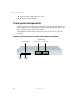
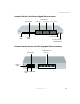
Switch descriptions Gateway 7201-24.2 fast Ethernet/gigabit Ethernet switch Speed LEDs Power LED Ports 1-8 Fast Ethernet Ports 9-16 Ports 17-24 Port 25 and LEDs Link/Act LEDs Port 26 and LEDs Gigabit Ethernet Gateway 7401-05 (shown) and 7401-08 gigabit Ethernet switches Gigabit Ethernet Speed LEDs Ports 1-5 Link/Act LEDs Power Duplex LEDs LED www.gateway.
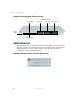
Chapter 1: Introduction Gateway 7401-24 gigabit Ethernet switch Speed LEDs Ports 1-8 Gigabit Ethernet Ports 9-16 Ports 17-24 Power LED Link/Act LEDs LED Indicators The LED indicators on the switches include Power, Link/Act, and Speed. The Gateway 7401-05 and 7401-08 also have a Duplex LED. The following shows the LED indicators for the various switches, and the table provides an explanation of what each LED indicates. Gateway 7401-05 (shown) and 7401-08 switches 6 www.gateway.
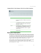
Switch descriptions Gateway 7201-16, 7201-24 (shown), 7201-24.2, and 7401-24 switches LED Indicates Power This indicator will light steady green immediately after the switch is powered on to indicate the ready state of the device. Link/Act This indicator lights green when the port is connected to a Gigabit Ethernet, Fast Ethernet, or Ethernet station. If the indicator is blinking green, data is either being transmitted or received.
Chapter 1: Introduction Side panel description The sides of the system provide heat vents that help to dissipate heat. Do not block these openings, and leave at least 6 inches (152.3 mm) of space at the rear and sides of the switch for correct ventilation. Warning 8 Without correct heat dissipation and air circulation, system components might overheat, which could lead to system failure. www.gateway.
Installation 2 This chapter provides you with information on how to install your Gateway switch.
Chapter 2: Installation Before you connect to the network The site where you install the switch may greatly affect its performance. Please follow these guidelines for setting up the switch: 10 ■ Install the switch on a sturdy, level surface that can support at least 6.6 lbs. (3 kg) of weight. Do not place heavy objects on the switch. ■ The power outlet should be within 6 feet (1.82 meters) of the switch. ■ Visually inspect the power cord and see that it is fully secured to the AC power port.
Installing the 5- and 8-port switches Installing the 5- and 8-port switches Package contents Open the shipping carton and carefully unpack its contents. The carton should contain the following items: ■ One Gateway 7401-05 5-port, or 7401-08 8-Port 10/100/1000BASE-T Gigabit Ethernet switch ■ Four rubber feet with adhesive backing ■ One external power adapter ■ This manual If any item is found missing or damaged, contact Gateway for a replacement.
Chapter 2: Installation After the switch is turned on, the LED indicators will momentarily blink, showing a reset of the system. Power failure If a power failure occurs, unplug the switch. When power is resumed, plug the switch back in. 12 www.gateway.
Installing the 16- and 24-port switches Installing the 16- and 24-port switches Package contents Open the shipping carton of the switch and carefully unpack its contents. The carton should contain the following items: ■ One Gateway 7201-16, 16-port or 7201-24, 24-port 10/100BASE-T Fast Ethernet switch, or 7401-24, 24-port 10/100/1000BASE-T Gigabit Ethernet switch, or 7401-24.2, 24-port + 2 10/100/1000BASE-T Gigabit Ethernet switch. ■ Accessory pack, including 2 mounting brackets and screws.
Chapter 2: Installation Installing the 16- and 24-port switches in a rack The switch can be mounted in a standard 19” rack. Use the following illustrations to guide you. Warning Before attaching rack mounting hardware, make sure that the switch is turned off and all power cords are unplugged. Warning The rack cabinet must provide sufficient airflow to the front of the switch to maintain correct cooling.
Installing the 16- and 24-port switches 3 With the assistance of another person, hold the switch in place in the rack and secure with two screws and nuts on each side (provided. 4 Install the cables and power cord. Power on Plug one end of the AC power cord into the power connector of the switch and the other end into the local power source outlet. After the switch is turned on, the LED indicators will momentarily blink. This blinking of the LED indicators represents a reset of the system.
Chapter 2: Installation 16 www.gateway.
Connecting the Switch 3 This chapter provides you with information on connecting Gateway unmanaged switches.
Chapter 3: Connecting the Switch Connecting to an end node For the Gateway 7201-16 and 7201-24 switches, end nodes include computers with 10, 100, or 10/100 Mbps RJ-45 Ethernet/Fast Ethernet Network Interface Cards (NIC). For the Gateway 7401-05, 7401-08, 7401-24, and 7201-24.2 switches, end nodes include computers with 10, 100, or 1000 Mbps RJ-45 Ethernet/Fast Ethernet/Gigabit Network Interface Cards (NIC). End nodes can also include most routers.
Connecting to a hub or switch Connecting to a hub or switch These connections can be accomplished in a number of ways using a standard Ethernet cable. ■ A 10BASE-T hub or switch can be connected to the switch through a twisted-pair Category 3, 4, 5, or 5e UTP/STP cable. Either straight-through or crossover cables can be used. ■ A 100BASE-TX hub or switch can be connected to the switch through a twisted-pair Category 5 UTP/STP cable. Either straight-through or crossover cables can be used.
Chapter 3: Connecting the Switch Connecting to a network backbone or server On all of the switches, any of the ports are satisfactory for uplinking to a network backbone or network server. On the Gateway 7201-24.2 switch, use one of the two Gigabit ports for optimum performance. These ports operate at 1000 Mbps in full-duplex mode. A valid connection is indicated when the Link LED is lit. 20 www.gateway.
Specifications A This chapter provides you with the specifications for Gateways’ unmanaged switches.
Appendix A: Specifications Gateway 7401-24 (24-port), gigabit Ethernet switch General Standards: IEEE 802.3ab 1000BASE-T Gigabit Ethernet IEEE 802.3u 100BASE-TX Fast Ethernet IEEE 802.3 10BASE-T Ethernet IEEE 802.3 NWay Auto-negotiation IEEE 802.
Physical & Environmental Storage Temperature: Humidity: 14 to 158 Fahrenheit (-10 to 70 degrees Celsius) Operating: 5% to 95% RH, non-condensing Storage: 0% to 95% RH, non-condensing Dimensions: 17.36 x 8.15 x 1.73 inches (440 mm x 210 mm x 44 mm) 1U, 19 inch rack-mount width Weight: 6.6 lbs. (3 Kg) Performance Transmission Method: Store-and-forward RAM Buffer: 2M bits per device Filtering Address Table: 4K MAC address per device MAC Address Learning: Self-learning, auto-aging www.gateway.
Appendix A: Specifications Gateway 7401-05 (5-port), and 7401-08 (8-port) gigabit Ethernet switches General Standards: IEEE 802.3ab 1000BASE-T Gigabit Ethernet IEEE 802.3u 100BASE-TX Fast Ethernet IEEE 802.3 10BASE-T Ethernet IEEE 802.3x Flow Control Protocols: CSMA/CD Data Transfer Rates: Ethernet: 10Mbps (Half-duplex) 20Mbps (Full-duplex) Fast Ethernet: 100Mbps (Half-duplex) 200Mbps (Full-duplex) Gigabit Ethernet: 2000Mbps (Full-duplex) Topology: Star Network Cables: Ethernet: 2-pair UTP Cat.
Physical & Environmental Storage Temperature: Humidity: 14 to 158 Fahrenheit (-10 to 70 degrees Celsius) Operating: 5% to 95% RH, non-condensing Storage: 0% to 95% RH, non-condensing Dimensions: 9.25 × 6.37 × 1.4 inches (235 mm × 161.9 mm × 35.6 mm) Weight: 6.6 lbs.
Appendix A: Specifications Gateway 7201-16 (16-port), and 7201-24 (24-port), fast Ethernet switches General Standards: IEEE 802.3u 100BASE-TX Fast Ethernet IEEE 802.3 10BASE-T Ethernet IEEE 802.3x Flow Control Protocols: CSMA/CD Data Transfer Rates: Ethernet: 10Mbps (Half-duplex) 20Mbps (Full-duplex) Fast Ethernet: 100Mbps (Half-duplex) 200Mbps (Full-duplex) Topology: Star Network Cables: Ethernet: 2-pair UTP Cat.
Physical & Environmental Weight: 6.6 lbs. (3Kg) Performance Transmission Method: Store-and-forward RAM Buffer: 1M Bytes per device Filtering Address Table: 4K MAC address per device Packet Filtering/Forward ing Rate: Full wire speed MAC Address Learning: Self-learning, auto-aging www.gateway.
Appendix A: Specifications Gateway 7201-24.2 (24-port), fast Ethernet switch + 2GTP switch General Standards: IEEE 802.3ab 1000BASE-T Gigabit Ethernet IEEE 802.3u 100BASE-TX Fast Ethernet IEEE 802.3 10BASE-T Ethernet IEEE 802.3x Flow Control Protocols: CSMA/CD Data Transfer Rates: Ethernet: 10Mbps (Half-duplex) 20Mbps (Full-duplex) Fast Ethernet: 100Mbps (Half-duplex) 200Mbps (Full-duplex) Gigabit Ethernet: 2000Mbps (Full-duplex) Topology: Star Network Cables: Ethernet: 2-pair UTP Cat.
Physical & Environmental Storage Temperature: Humidity: 14 to 158 Fahrenheit (-10 to 70 degrees Celsius) Operating: 5% to 95% RH, non-condensing Storage: 0% to 95% RH, non-condensing Dimensions: 5.55 × 8.15 × 1.69 inches (441 mm × 207 mm × 43 mm) Weight: 6.6 lbs.
Appendix A: Specifications 30 www.gateway.
Safety, Regulatory, and Legal Information B Important safety information Your Gateway switch is designed and tested to meet the latest standards for safety of information technology equipment. However, to ensure safe use of this product, it is important that the safety instructions marked on the product and in the documentation are followed. Warning Always follow these instructions to help guard against personal injury and damage to your Gateway switch.
Appendix B: Safety, Regulatory, and Legal Information Setting up your switch ■ Read and follow all instructions marked on the product and in the documentation before you operate your switch. Retain all safety and operating instructions for future use. ■ Do not use this product near water or a heat source such as a radiator. ■ Set up the switch on a stable work surface. ■ The product should be operated only from the type of power source indicated on the rating label.
Important safety information Do not step on or stand on any component when servicing other components in a rack. Important A qualified electrician must perform all connections to DC power and to safety grounds. All electrical wiring must comply with applicable local or national codes and practices. Warning Never defeat the ground conductor or operate the equipment in the absence of a suitably installed ground conductor.
Appendix B: Safety, Regulatory, and Legal Information ■ Touch a bare metal surface on the back of the computer. ■ Unplug the power cord and the modem and network cables. Before working with computer components, follow these guidelines: ■ Avoid static-causing surfaces such as carpeted floors, plastic, and packing foam. ■ Remove components from their antistatic bags only when you are ready to use them.
Regulatory compliance statements Regulatory compliance statements United States of America Federal Communications Commission (FCC) Unintentional emitter per FCC Part 15 This device has been tested and found to comply with the limits for a Class B digital device, pursuant to Part 15 of the FCC rules. These limits are designed to provide reasonable protection against harmful interference in a residential installation.
Appendix B: Safety, Regulatory, and Legal Information This device complies with Part 15 of the FCC Rules. Operation of this product is subject to the following two conditions: (1) this device may not cause harmful interference, and (2) this device must accept any interference received, including interference that may cause undesired operation. Caution Changes or modifications not expressly approved by Gateway could void the FCC compliance and negate your authority to operate the product.
Notices Notices Copyright © 2004 Gateway, Inc. All Rights Reserved 14303 Gateway Place Poway, CA 92064 USA All Rights Reserved This publication is protected by copyright and all rights are reserved. No part of it may be reproduced or transmitted by any means or in any form, without prior consent in writing from Gateway. The information in this manual has been carefully checked and is believed to be accurate. However, changes are made periodically.
Appendix B: Safety, Regulatory, and Legal Information 38 www.gateway.
Index Numerics F 16-port switch installing 13 installing in rack 14 installing without rack 13 power on 15 24-port switch installing 13 installing in rack 14 installing without rack 13 power on 15 5-port switch installing 11 power on 11 8-port switch installing 11 power on 11 features, switch 3 front panel components 4 A L accessories safety precautions 34 LED indicators 6 G gigabit technology 2 H hub or switch connection 19 I indicators, LED 6 installing 16-port switch 13 24-port switch 13 5-port
T technology gigabit 2 switching 2 40
MAN UNMNGD ETH SWITCH GDE R0 1/04