
Logic HE Range Conventional Flue Log Effect Installation User Instructions


38
Servicing Instructions - Replacing Parts
8a.7 The gas valve can now be removed from the burner unit.
8a.8 To replace the gas valve reverse the above procedure.
NOTE: Ensure the correct orientation of the connections
when replacing, see Diagram 19 detail.
8a.9 Check for gas leaks.
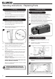
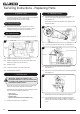
8b. Slide Control
8b.1 To remove the gas valve first remove the thermocouple,
see Diagram 22, Arrow A.
D
22
A
C
B
8b.2 Undo the pilot pipe from the gas valve, see Diagram 22,
Arrow B.
8b.3 Undo the inlet pipe from the gas valve, see Diagram 22,
Arrow C.
8b.4 Undo the main injector feed pipe from the gas valve,
see Diagram 22, Arrow D.
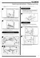
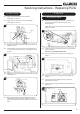
8b.5 Disconnect the 2 leads from the micro-switch, see
Diagram 23.
23
Leads
Micro Switch
Bracket
8b.6 Undo the screw from the end of the spindle and remove the
bracket, see Diagram 23 Ensure bracket is replaced during
reassembly.
8b.7 Remove the two screws from the gas valve, see
Diagram 23.
8b.8 Replace in reverse order.
8b.9 Check for gas leaks.
9. Micro-Switch
(Slide Control Model only)
9.1 Disconnect the two leads from the Micro-Switch, see
Diagram 23.
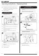
9.2 Remove the screw, bracket, washer & spacer from the
Micro-Switch spindle, see Diagrams 24 & 25.
24
25
Screw
Spacer
Bracket
Washer
When replacing ensure that the components are
assembled in the same order.
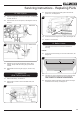
9.3 Remove the circlip from the spindle, see Diagram 26.
26
Circlip
Micro-Switch
9.4 Replace the micro-switch.
Reassemble in reverse order.