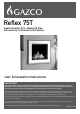
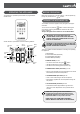
Reflex 75T Inset Convector Fire - Balanced Flue with Harmony 10 Remote Control System User & Installation Instructions IMPORTANT THE OUTER CASING, FRONT AND GLASS PANEL BECOME EXTREMELY HOT DURING OPERATION AND WILL RESULT IN SERIOUS INJURY AND BURNS IF TOUCHED. IT IS THEREFORE RECOMMENDED THAT A FIREGUARD COMPLYING WITH BS 8423 (LATEST EDITION) IS USED IN THE PRESENCE OF YOUNG CHILDREN, THE ELDERLY OR INFIRM. This product contains a Heat resistant glass panel.
CONTENTS REFLEX 75T - BALANCED FLUE Covering the following models: REFLEX 75T NAT GAS REFLEX 75T LPG Black Reeded 191-082 191-471 Vermiculite 191-094 191-487 Brick Effect 191-106 191-490 Ledgestone 191-111 191-512 Black Glass 191-127 191-528 Appliance Commissioning Checklist.......................3 User Instructions........................................................4 Installation Instructions...........................................12 Technical Specifications.......................
APPLIANCE COMMISSIONING CHECKLIST To assist us in any guarantee claim please complete the following information:- IMPORTANT NOTICE Explain the operation of the appliance to the end user, hand the completed instructions to them for safe keeping, as the information will be required when making any guaranteed claims. FLUE CHECK PASS FAIL 1. Flue Is correct for appliance 2. Flue flow Test N/A 3. Spillage Test N/A GAS CHECK 1. Gas soundness & let by test 2. Standing gas pressure mb 3.
GENERAL Installation and servicing must only be carried out by a competent person whose name appears on the Gas Safe register. To ensure the engineer is registered with Gas Safe they should possess an ID Card carrying the following logo: In all correspondence, please quote the appliance type and serial number, which can be found on the data badge located on a plate under the Main Burner.
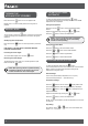
BEFORE OPERATING OPERATING THE APPLIANCE The appliance is operated by thermostatic and programmable remote control. Make sure manual knob on the gas valve is in the ON position by turning fully clockwise to the position. TURNING THE APPLIANCE ON The handset controls the appliance from pilot ignition through to shut down. To turn the fire on press the button until two short signals and a series of blinking series of lines confirm the start of the ignition sequence.
TURNING THE APPLIANCE OFF (STANDBY) Press and hold the button to turn the appliance off. NOTE: There is a 5 second delay before the next ignition is possible. To turn the fire on press the button until two short signals and a series of blinking series of lines confirm the start of the ignition sequence. Standby By (Pilot Flame) Mode: button to set the appliance to pilot flame FOR SAFETY, YOU MUST WAIT 30 SECONDS BEFORE LIGHTING THE FIRE AGAIN.
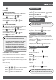
Press the ECOFLEX MODE button to confirm. ALL Selected Turning the EcoFlex Mode on. ON TIME SETTING (PROGRAM 1): , 1 ON displayed, ALL is displayed shortly and hour flashes. Select the hour by pressing the or button. button to confirm. , 1 ON displayed, ALL is Press the displayed shortly and minutes flashes. Select the minutes by pressing the Press the or button. button to confirm. , 1 OFF displayed, ALL is displayed shortly and hour flashes. or button. button to confirm.
COUNTDOWN TIMER SETTING FAHRENHEIT OR CELSIUS Turning the Timer on. Press and hold the flashes. button until To select the hour press the To confirm press the or button. button. Minutes flash. To select the minutes press the To confirm press the displayed, and hour or button. button or wait. Turning the Timer off. Press and hold the disappear. button, and countdown display will At the end of countdown time period, the appliance turns off.
MYFIRE WI-FI KIT This appliance can be fitted with an optional Wi-Fi kit which can allow operation from a tablet or smart device: Gazco part No. 999-055. Contact your Gazco retailer for more information. It may be necessary to reset the MyFire Wi-Fi box using a paperclip or similar,. The table below shows the length of time required for each reset and the confirmation signals.
FLAME FAILURE DEVICE APPLIANCE WILL NOT LIGHT This is a safety feature incorporated on this appliance which automatically switches off the gas supply if the pilot goes out and fails to heat the thermocouple. If you cannot light the appliance: IF THIS OCCURS DO NOT ATTEMPT TO RELIGHT THE APPLIANCE FOR 3 MINUTES. Consult your Gazco retailer or installer if the appliance still does not light.
INSTALLATION APPLIANCE LOCATION This appliance is designed for studwork installations. This appliance must not be installed in a room that contains a bath or shower. Combustible parts of the studwork must not be any closer than the minimum dimensions shown in the diagrams. NOTE: These dimensions must be maintained even if the combustible materials is protected by non-combustible linings. Do not pack the void around or above the appliance with insulation materials such as mineral wool.
FLUE & CHIMNEY REQUIREMENTS Note: This appliance must only be installed with the flue supplied. The following: must be adhered to: The flue must be sited in accordance with BS5440: Part 1 (latest edition). Fit a guard to protect people from any terminal less than 2 metres above any access such as level ground, a balcony or above a flat roof. All vertical and horizontal flues must be securely fixed and fire precautions followed in accordance with local and national codes of practice.
DIMENSIONS 801 400 361 344 17 896 211 711 868 952 754 745 109 877 427 13
TECHNICAL SPECIFICATION Covering the following models: REFLEX 75T NAT GAS REFLEX 75T LPG Black Reeded 191-082 191-471 Vermiculite 191-094 191-487 Brick Effect 191-106 191-490 Ledgestone 191-111 191-512 Black Glass 191-127 191-528 MODEL GAS CAT. GAS TYPE WORKING PRESSURE GAS RATE M3/H Reflex 75T I2H Nat Gas G20 18mbar Reflex 75T I3+ LPG G31 37mbar INPUT KW (GROSS) HIGH LOW 0.953 10.0 4.1 0.369 9.8 4.
TECHNICAL SPECIFICATION INJECTOR TABLE REAR REAR REAR Nat Gas S120 Nat Gas S128 LPG S63 LPG S78 Nat Gas S102 LPG S63 Rear of appliance Front of appliance FRONT Nat Gas S92 LPG S60 FRONT FRONT Nat Gas S92 LPG S60 Nat Gas S88 LPG S60 NOTE: Aeration Holes are in each leg of the burners. These holes are different sizes at the Front and Back for each individual leg. REAR REAR REAR Nat Gas 5.0 (x2) Nat Gas 5.5 (x2) Nat Gas LPG 6.5 (x2) LPG 9.0 (x2) LPG 6.0 7.
TECHNICAL SPECIFICATION RESTRICTOR TABLES RESTRICTOR REQUIREMENT - VERTICAL & HORIZONTAL FLUE SPECIFICATION Vertical flue height from top of appliance Horizontal length Restrictor size 500mm - 999mm Up to 500mm N/A 1000mm - 1499mm Up to 1000mm N/A 1500mm - 3000mm Up to 5000mm N/A TOP EXIT - VERTICAL ONLY INCLUDING OFFSET (8" WITH 6" ADAPTER) Vertical flue height from top of appliance Restrictor size 1500mm - 1999mm 70mm 2000mm - 4999mm 60mm 5000mm - 10000mm 52mm This appliance has been c
Earth Mains Power In Light Supply Dimmable LED Ignition Lead SW Lead Control Box Control Value Thermocouple Electric Module Pilot Burner Control Valve Supply Wi-Fi Module (Optional) Solenoid Supply Lead TC Lead Solenoid Valve WIRING DIAGRAM 17
FLUE OPTIONS REAR FLUE TIMBER FRAMED BUILDINGS It will be necessary to provide additional clearance when the flue passes through a wall containing any combustible materials so as to prevent a fire hazard. The hole through which the flue will pass, must have a steel sleeve which is positioned so that an air gap of at least 25mm is maintained between the outer surface of the flue, and any part of the sleeve.
FLUE OPTIONS TOP FLUE UP AND OUT WITH ADDITIONAL BEND TOP FLUE VERTICAL KIT (8524) Any additional bend may be used on the horizontal section (either 45° or 90°), but the overall horizontal flue run will be reduced. This flue is vertical from the top of the appliance. A minimum vertical rise of 1.5m (4’9”) to a maximum of 10m (32’10”).
FLUE OPTIONS OPTIONAL EXTRA FLUE LENGTHS AND BENDS All flue components are 150mm diameter (6") NOMINAL LENGTH ACTUAL LENGTH STAINLESS FINISH ANTHRACITE FINISH 200mm* 140mm* 8527 8527AN 500mm* 440mm* 8528 8528AN 1000mm* 940mm* 8529 8529AN *Not including adapter dimensions NOTE: The following areas need careful consideration. a) Terminal positions b) Flue supports c) Weatherproofing d) Fire precautions For all the above options, local and national codes of practice must be adhered to.
SITE REQUIREMENTS If fitting this appliance with a decorative frame it cannot be installed with the base of the appliance less than 150mm from the floor level. The frame requires a minimum clearance to allow air to circulate. If this appliance is fitted less than 225mm from the floor, then it will require a hearth to protect the floor. The hearth should have a minimum dimension of 12mm thick, projecting 225mm in front and 150mm either side of the appliance.
SITE REQUIREMENTS MASONRY INSTALLATION Please note this appliance has been primarily designed for studwork applications. However, there are circumstances where the appliance could be installed in a block or brickwork fireplace using different methods and materials for the final effect. THIS VOID MUST BE VENTED TO PREVENT HEAT BUILD UP AROUND THE APPLIANCE.
PRE-INSTALLATION REMOVING THE GLASS 5 1 1 1 2 2 2 Remove the 2 boxes from the appliance and store safely as they contain the Log Burners and fuel effects.
PRE-INSTALLATION 3 Disconnect the Mains Lead Plug, the LED leads and the receiver lead from the Module and the Wi-Fi box (if installed). DO NOT REMOVE THE WIRES FROM THE PLUG.
PRE-INSTALLATION 9 NOTE: Take care not to catch any loose wiring previously disconnected against the front edge of the firebox. The gas supply enters through the Silicone Panel located on the left-hand rear of the outer box; this will need to be slit with a sharp knife prior to passing the supply pipe through. 10 Note: The Isolation Elbow needs to be attached to the gas pipe before installation.
FLUE ASSEMBLY TAKE CARE WHEN MARKING OUT FOR THE FLUE AS IT IS DIFFICULT TO MOVE AFTER INSTALLATION. IF A RESTRICTOR IS REQUIRED FIT THIS BETWEEN THE SMALL OUTLET SPIGOT AND THE AIR DUCT. REFER TO TECHNICAL SPECIFICATIONS FOR RESTRICTOR SIZE. A 203mm (8") diameter hole in the wall is required to install the flue. This can be achieved by using either: a) Core drill b) Hammer and chisel Drill small holes around the circumference when using method b). Make good both ends of the hole.
MASONRY INSTALLATION There are 2 methods of installation into a masonry chimney: Edge finish Installation. Installation with a decorative front. Carefully read the relevant section for the installation method required. This appliance is designed so that non-combustible board can be taken right up to the edge of the flange. It is necessary to be able to disconnect the appliance from the mains electrical supply after installation.
MASONRY INSTALLATION DECORATIVE FRAME INSTALLATION 3 Mantels, Hearths & Slips If fitting this appliance with a decorative surround it will be necessary to install the appliance with a Hearth and Slip set. The hearth must have a minimum depth of 225mm. It is essential to ensure that a height of 123mm is maintained from the finished floor to the bottom edge of the viewing area. Read these instructions in conjunction with the manual supplied before installation.
STUDWORK ENCLOSURE CONSTRUCTION Example enclosure VENTILATION The void into which the cassette is fitted must be ventilated to prevent a build up of heat. If the void is sealed then it will be necessary to fit high and low level vents on both sides of the enclosure with a minimum vent size of 200cm2 open free area each. These vents should take cold air from the room and return warm air back into the room.
CUTTING TEMPLATES B Upper Front Panel B Lower Front Panel A A D C Inner Side Panel x2 B B Side Panel x2 A C D A PANEL A (MIN) B (MIN) C D Upper Front Panel 949mm 400mm - - Lower Front Panel 949mm 129mm No Frame 150mm - Decorative Frame - - Side Panel 404mm 901mm No Frame 940mm - Decorative Frame 100 30 Inner Side Panel 150mm 370mm - - 30
EDGE FRAME INSTALLATION 1 4 5 2 3 6 31
EDGE FRAME INSTALLATION 7 8 9 32
DECORATIVE FRAME STUDWORK INSTALLATION IMPORTANT: BEFORE THE INSTALLATION OF THE DECORATIVE FRONT ENSURE THAT THE WALL ABOVE AND TO THE SIDES OF THE APPLIANCE IS SUITABLY CONSTRUCTED FOR THE FIXINGS TO SUPPORT THE WEIGHT OF THE FRONT. IF THE WALL IS CONSTRUCTED FROM PLASTERBOARD OR SIMILAR, IT IS ESSENTIAL THAT BATTERNS ARE LOCATED TO THE SIDES OF THE APPLIANCE IN THE FIXING AREA TO PROVIDE STRENGTH TO THE FIXINGS.
DECORATIVE FRAME STUDWORK INSTALLATION 5 6 7 34 8 9 10
FITTING THE MAIN CONTROL ASSEMBLY 11 Please note: If you intend to install a MyFire Wi-Fi App with the Reflex 75T it is easier to attach the wire for the reciever box at this stage. The module and wires for the App can be fitted after installation but access is easier with the Control Box exposed. Ensure the LED cable and Receiver cable are fed under the front of the firebox aperture and are not trapped. NOTE: If fitting a Wi-Fi module, the Wi-Fi cable must also be fed under the firebox aperture.
Reconnect the Mains Lead Plug, the LED leads and the receiver lead from the Module and the Wi-Fi box (if installed), 4 GAS SOUNDNESS PRESSURE CHECK Connect a pressure gauge to the test point 1 Elbow 5 Turn the gas supply on. Loosely place the appropriate burners onto the injectors. Light the appliance and check all gas joints for possible leaks. Turn the appliance to maximum and check that the supply pressure is as stated on the databadge. Turn the appliance off.
3 ASSEMBLING THE FUEL BED 1 3 2 1 2 1 NOTE: RH BURNER IS SHORTER. 4 2 ARRANGEMENT OF FUEL BED COMPONENTS TAKE CARE NOT TO SPILL THE FUEL EFFECT INTO THE PILOT AREA. ONLY GENUINE GAZCO PARTS CAN BE USED IN THIS APPLIANCE. Use the entire bag of supplied Amber Effect. The Shale Effect is supplied as large pieces which will need to be broken into 2-3 smaller shards before placing onto the fuel bed. It is not necessary to use all the supplied Shale Effect.
LOG LAYOUT 3 B D C A F 1 E H G G A H E F 4 B F 2 G H ≈75 % � X 38
5 C 15mm 7 E C 8 6 D ≈25 % A A D A 9 D 39
3 WARNING - DO NOT PLACE 4 2 1 COMPLETION OF ASSEMBLY REPLACE ALL OF THE SECURING SCREWS, ENSURING THAT A SCREW IS PRESENT IN ALL FIXING SLOTS. 1 UNDER NO CIRCUMSTANCES SHOULD THE APPLIANCE BE USED IF ANY OF THE GLASS FRAME RETAINING SCREWS RE LOOSE OR MISSING. 1 NEVER OPERATE THE APPLIANCE WHEN THE GLASS PANEL IS REMOVED OR BROKEN. Replace the decorative front by referring to the separate leaflet supplied with the front.
LIGHTING THE APPLIANCE The appliance is operated by thermostatic and programmable remote control. TURNING THE APPLIANCE OFF (STANDBY) Press and hold the button to turn the appliance off. NOTE: There is a 5 second delay before the next ignition is possible. TROUBLESHOOTING IMPORTANT: In the unlikely event that the handset fails to communicate correctly with the appliance it may be necessary to turn off the gas supply at the isolation valve until any problems can be resolved.
MYFIRE WI-FI INSTALLATION BEFORE UNDERTAKING ANY WORK SWITCH OFF THE APPLIANCE AND ISOLATE THE POWER SUPPLY ENSURING THERE IS NO POWER TO THE APPLIANCE. Ensure the module lead runs underneath the front panel spacer. 4 Remove the Front Glass. Front Panel Spacer Remove the 3 screws securing the Cam Lock Brackets and the Glass Support bracket. 1 Front Panel removed for clarity This should complete the wiring circuit as shown. 5 Wi-Fi Router Lift the brackets away from the appliance.
MYFIRE WI-FI SET UP & TROUBLESHOOTING It may be necessary to reset the MyFire Wi-Fi box using a paperclip or similar. The table below shows the length of time required for each reset and the confirmation signals. The MyFire Wi-Fi box must be wired according to the MyFire set up diagram and connected to the receiver, which is in turn connected to the mains power. Ensure the device is running the most up to date operating system as older models may not be compatible with the MyFire App.
COMMISSIONING Complete the Commissioning Checklist at the front of this manual covering: — Thermocouple soundness checks. This is to include ensuring the thermocouple is secure on the pilot bracket assembly, lead connection and integrity. — Flue checks — Gas checks — Log layout - flame picture REPROGRAMMING HANDSET/ CONTROL BOX To access the control box: Remove the decorative trim, see Servicing Instructions. Remove the lower glass retaining bracket, see Servicing Instructions, Page 40.
SERVICING REQUIREMENTS IMPORTANT – The glass panels on this appliance should be checked for any signs of damage on the front face of the glass panel (scratches, scores, cracks or other surface defects). If damage is observed, the glass panel must be replaced and the appliance must not be used until a replacement is installed. Under no circumstances should the appliance be used if any damage is observed. Please isolate the appliance until a replacement glass panel has been obtained and installed.
FAULT FINDING CHARTS IGNITION FUNCTIONAL CHECK 1 PILOT WILL NOT LIGHT Ensure there is no debris around the pilot assembly, (e.g. soot, etc.) which could short the spark, clean the area. No Yes Operate the valve. Is there a spark? Yes Does the pilot light? No Consult User Instructions and retry.
Replace the combined lead and piezo, retry. No Is the electrode wire detached from the piezo in the valve? No Replace the electrode. Yes Yes No No Correct and retry. Reset the pilot burner. Is the control system being operated correctly? Yes Yes Replace the piezo and gas valve and retry. No Remove the electrode lead from the piezo. Operate the valve. Does a spark jump from the piezo to the valve body? Check for defective or damaged control knob spindle or cam operation.
3 GENERAL All main components can be replaced without removing the appliance from its installation. DISCONNECT MAINS ELECTRICAL SUPPLY AT THE ACCESSIBLE PLUG OR DEDICATED SWITCH BEFORE SERVICING THE APPLIANCE. IT IS ESSENTIAL THAT THE GAS SUPPLY TO THE APPLIANCE IS TURNED OFF AT THE ISOLATION DEVICE BEFORE PROCEEDING FURTHER. It will be necessary to remove the burners and the fuel bed before any of the main components can be serviced.
REMOVING THE FUEL EFFECT 2 1 3 The fuel effect consists of 6 different components. 2 To avoid damage Logs A, B, C and D should be removed in the following order and placed on a dry, clean surface. 1 B D C 3 2 A 4 Remove the remaining components: Log E. Embers F, G and H. 2 small Embers. Shale Effect. Amber Effect. 2 1 Keep each component separate for ease of replacing.
Turn the gas supply off at the isolation device. HAVE YOU ISOLATED THE GAS SUPPLY? Disconnect the isolating device from the appliance inlet pipe to isolate the gas supply. Disconnect the LED lead and the Receiver lead from the power module, if fitted, disconnect the Wi-Fi lead from the Wi-Fi module (if installed. 10 6 Elbow 11 7 8 12 9 AFTER SERVICING ENSURE THAT ALL CONNECTIONS ARE REPLACED BEFORE REPLACING THE MESH TRAY.
REPLACING THE LED CIRCUIT There are 3 LED boards, which can be replaced individually. Remove the 2 screws holding the LED boards to the Control Assembly by inserting a screwdriver through the gap previously covered by the glass bracket. 3 Driver Front LED 1 Rear LED bar Front LED 2 THE LED'S ARE FRAGILE. HANDLE WITH CARE. ONLY HOLD THE LED BOARDS BY THE EDGES TO AVOID CONTACT WITH THE TOP OF THE LED'S. AVOID CATCHING ANY DELICATE WIRES WHEN REPLACING THE SCREWS. The boards can now be replaced.
The pilot assembly consists of three components, which can be individually changed, these are: REPLACING THE MODULE Electrode. Pilot Injector. Thermocouple. Remove the module bracket and disconnect the LED plug and Mains Lead from the Module. Mains Lead 2 Thermocouple Screw Electrode Pilot Injector Screws Pilot Pipe Module Lead Ignition Lead LED Plug ELECTRODE Disconnect the Module Lead. 3 The Module can now be removed. Replace in reverse order.
THERMOCOUPLE 5 GAS VALVE 1 Screw C D A E B Screw IGNITION LEAD 1 To change the gas valve: Disconnect the Gas Inlet Pipe, Arrow A. Disconnect the Gas Outlet Pipe, Arrow B. Disconnect the Pilot Pipe, Arrow C. Disconnect the Thermocouple, Thermocurrent Wires and the Interrupter Block, Arrow D. Remove the Eight Wire Loom, Arrow E. There is an access hole in the top of the Control Bracket to release the locking tab. Carefully cut cable ties from the vidaflex and disconnect the lead from the electrode.
CONTROL BOX Cut the cable tie holding the Ignition lead and the Thermocurrent cables. Disconnect the Module and Solenoid leads from the Control Box. 1 8-way Cable Note: When pressing the DOWN button on the handset if two beeps are not heard: — Release the DOWN button and CONN will be displayed on the handset screen. An 8 second count will start on the handset screen followed by two short beeps confirming the new code is set.
Replace with the correct size Injector. DO NOT OVERTIGHTEN. Replace with the correct size Injector and refit all components in the reverse order. Use thread sealant Loctite 572 when replacing Injectors. Check for leaks. Repeat for the remaining Injectors. LATCHING SOLENOID Check for leaks. CROSS LIGHTING INJECTOR 1 Pipes and wires removed for clarity 2 Pipes and wires removed for clarity Turn the Main Control Assembly over to access the components on the underside.
CHANGING BETWEEN GAS TYPES 2 In order to change between gas types, it will be necessary to change the following components: Pilot Main Injectors x 6 Crosslighting Injector Gas Valve Main Burner x 3 Contact your Gazco retailer for further information. A kit of parts is available for this. Always quote the Model number and Serial number when ordering any spare parts.
Withdraw the old cable. 5b Fit the new cable in reverse order ensuring it is rewired in the correct configuration. 1 2 Re-assemble in reverse order. REPLACING THE POWER CABLE BEFORE UNDERTAKING ANY WORK SWITCH OFF THE APPLIANCE AND ISOLATE THE POWER SUPPLY ENSURING THERE IS NO POWER TO THE APPLIANCE. To replace the Power Cable first remove the Main Control Assembly. Disconnect the 3 cables from the Power Module (A). NOTE THE CONFIGURATION OF THE WIRES.
SPARES LIST - MAIN ASSEMBLY PART CODE PART CODE NO. COMPONENT NATURAL GAS LPG CE1731 QTY.
SPARES LIST - CONTROL ASSEMBLY PART CODE NO. COMPONENT NATURAL GAS LPG PART CODE QTY. NO. COMPONENT NATURAL GAS LPG QTY.
Reflex 75T MkII BF NG Reflex 75T MkII BF LPG 130 130 Nominal Heat Output - Pnom 8.3kW 8.3kW Minimum Heat Output (indicative) -Pmin 2.8kW 3.0kW Auxiliary Electricity Consumption At Nominal Heat Output - elmax 0.003kW 0.003kW At Minimum Heat Output - elmin 0.003kW 0.003kW In Standby Mode - elsb 0.003kW 0.003kW Useful Efficiency (NCV) INFORMATION REQUIREMENT FOR GASEOUS FUEL LOCAL SPACE HEATER Useful Efficiency at nominal heat output - ηth,nom 92.0% 92.
SERVICE RECORDS 1ST SERVICE 2ND SERVICE Date of Service........................................................................... Date of Service......................................................................... Next Service Due....................................................................... Next Service Due..................................................................... Signed........................................................................................ Signed..........
Gazco Ltd, Osprey Road, Sowton Industrial Estate, Exeter, Devon, England EX2 7JG Tel: (01392) 474011 Fax: (01392) 219932 E-mail: info@gazco.com www.gazco.