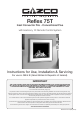
Reflex 75T Inset Convector Fire - Conventional Flue with Harmony 10 Remote Control System Instructions for Use, Installation & Servicing For use in GB & IE (Great Britain & Republic of Ireland). IMPORTANT THE OUTER CASING, FRONT AND GLASS PANEL BECOME EXTREMELY HOT DURING OPERATION AND WILL RESULT IN SERIOUS INJURY AND BURNS IF TOUCHED. IT IS THEREFORE RECOMMENDED THAT A FIREGUARD COMPLYING WITH BS 8423 (LATEST EDITION) IS USED IN THE PRESENCE OF YOUNG CHILDREN, THE ELDERLY OR INFIRM.
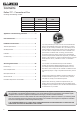
Contents Reflex 75T - Conventional Flue Covering the following models: Reflex 75T Nat Gas Reflex 75T LPG Black Reeded 191-029 191-412 Vermiculite 191-033 191-424 Brick Effect 191-045 191-435 Ledgestone 191-051 191-448 Black Glass 191-062 191-459 Appliance Commissioning Checklist.......................3 User Instructions........................................................4 Installation Instructions...........................................11 Technical Specifications ..................
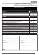
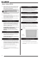
Appliance Commissioning Checklist To assist us in any guarantee claim please complete the following information:- IMPORTANT NOTICE Explain the operation of the appliance to the end user, hand the completed instructions to them for safe keeping, as the information will be required when making any guaranteed claims. FLUE CHECK PASS FAIL 1. Flue Is correct for appliance 2. Flue flow Test 3. Spillage Test GAS CHECK 1. Gas soundness & let by test 2. Standing gas pressure mb 3.
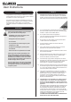
User Instructions 1. General Welcome Congratulations on purchasing your Reflex fire, if installed correctly Gazco hope it will give you many years of warmth and pleasure for which it was designed. 1.1 Installation and servicing must only be carried out by a competent person whose name appears on the GasSafe register. To ensure the engineer is registered with GasSafe they should possess an ID Card carrying the following logo: 1.
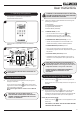
User Instructions 2. Operating the Appliance WARNING: IF THE APPLIANCE FAILS TO LIGHT OR BECOMES EXTINGUISHED IN USE, WAIT 3 MINUTES BEFORE ATTEMPTING TO RELIGHT. The appliance is operated by thermostatic and programmable remote control. 2.2 1 There are 4 different modes available for controlling and operating the appliance: 1. Manual Mode 2. Thermostatic Mode (Automatic) 3. Program Mode (Automatic) 4. EcoFlex Mode (Automatic) 2.3 In MANUAL MODE you can: — turn on the main burner using the button.
User Instructions Increasing the Flame Height: To increase flame height press and hold button. Decreasing the Flame Height: To decrease flame height or to set the appliance to pilot flame press and hold the button. NOTE: While pressing a button a symbol indicating transmission appears on the display. The receiver confirms transmission with a sound signal. Setting the temperature: button until the temperature Adjust the temperature by pressing the button. Press the or button to confirm the temperature.
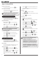
User Instructions SA:SU or Daily (1, 2, 3, 4, 5, 6, 7) selected Set On and Off time using the same procedure as 'ALL Selected' (above). Light Operation Turning the light on. SA:SU: Set On and Off time for both Saturday and Sunday. Press the Daily Timer: Unique On and Off times might be set for a single day of the week, for multiple days of the week, or for every day of the week. The light is on at preset level. Wait to finish setting. Press the Mode.
User Instructions MyFire Wi-Fi Troubleshooting Setting the time Press the flashes. and buttons simultaneously. Day 2.9 Press the or button to select a number that corresponds with a day of the week (eg 1 = Monday, 2 = Tuesday, 3 = Wednesday, 4 = Thursday, 5 = Friday, 6 = Saturday, 7 = Sunday). Press the flashes. and Press the flash. and or After 30 seconds the MyFire Box goes into Access Point Mode (Green LED flashes). See MyFire App instructions supplied and configure the router. button. 2.
User Instructions Press Reset Button LED Status Blue Power LED Function 1 Sec Continuously flashes every ½ second Activates Access Point Mode for 10mins (connect MyFire Wi-Fi module to home network). Simultaneously the Wi-Fi channel changes. 5 Secs Two rapid flashes every 1 second System Reset. 10 Secs Flashes every 100 milliseconds (Continuous) Restore factory firmware (MyFire Wi-Fi module will set to default after reboot); takes up to 2 minutes.
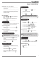
User Instructions 3.13 Replace the screws. As the screws are tightened the glass frame is pulled down against the hooks and forms a seal. Replace ALL of the securing screws ensuring that a screw is present in all fixing slots. 7. Servicing 7.1 UNDER NO CIRCUMSTANCES SHOULD THE APPLIANCE BE USED IF ANY OF THE GLASS FRAME RETAINING SCREWS ARE LOOSE OR MISSING. 3.14 Replace the lower trim. 3.15 Replace the 2 magnetic side trims. The appliance must be serviced every 12 months by a qualified Gas Engineer.
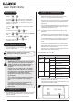
Installation Instructions Technical Specification Covering the following models: Reflex 75T Nat Gas Reflex 75T LPG Black Reeded 191-029 191-412 Vermiculite 191-033 191-424 Brick Effect 191-045 191-435 Ledgestone 191-051 191-448 Black Glass 191-062 191-459 Model Gas CAT. Gas Type Working Pressure Gas Rate m3/h Reflex 75T I2H Natural Gas G20 20mbar Reflex 75T I3+ Propane G31 37mbar Input kW (Gross) High Low 1.096 11.5 4.8 0.433 11.5 4.
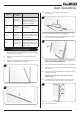
Installation Instructions Injector Table REAR REAR REAR Nat Gas S120 Nat Gas S125 Nat Gas S104 LPG S71 LPG S88 LPG S71 Rear of appliance Front of appliance FRONT FRONT FRONT Nat Gas S104 Nat Gas S92 Nat Gas S92 LPG S60 LPG S63 LPG S60 Wiring Diagram LED Pilot Burner Control Value Thermocouple Earth SW Lead Light Supply Solenoid Valve Control Valve Supply TC Lead Solenoid Supply Lead Ignition Lead Control Box Electric Module Mains Power In 12 Wi-Fi Module (Option
Installation Instructions Technical Specification This appliance has been certified for use in countries other than those stated. To install this appliance in these countries, it is essential to obtain the translated instructions and in some cases the appliance will require modification. Contact Gazco for further information. PACKING CHECKLIST Qty.
Installation Instructions Site Requirements 1. Flue & Chimney Requirements WHEN INSTALLING A FLUE SYSTEM PLEASE REFER TO THE MANUFACTURER’S INSTRUCTIONS. The European chimney standards now describe chimneys and flues by their temperature, pressure and resistance to corrosion, condensation and fire. To identify the correct flue system, the minimum flue specification is shown in the Technical Specification. Existing chimneys are not covered by this system. 3.
Installation Instructions Site Requirements 5.3 5.4 NOTE: If using natural materials for the back panel of the fireplace, it is recommended that it is constructed from three or more sections to prevent cracking. Resin based materials may not be suitable. This appliance is an effective heat producer and attention must be paid to the construction and finish of the fireplace. When the appliance is installed in a masonry chimney without a liner, there must be a minimum debris collection area, see Diagram 2.
Installation Instructions 1. Safety Precautions 1.1 These instructions must be left intact with the user. 1.3 Do not attempt to burn rubbish on this appliance. 1.4 Keep all plastic bags away from young children. 1.5 Do not place any object on or near to the appliance and allow adequate clearance above the appliance. IF THE APPLIANCE IS EXTINGUISHED OR GOES OUT IN USE, WAIT 3 MINUTES BEFORE ATTEMPTING TO RELIGHT THE APPLIANCE.
Installation Instructions 2.9 If a flexible liner is to be used check the seal on the inner lip of the spigot plate is intact. Replace if necessary. 3.4 Pull up the handle at the front, see Diagram 6. 3.5 Whilst supporting the top, lift the door using the handle, up and over the lower edge, see Diagram 7. 3 7 Options 3 and 4 (Studwork with Edge finish or decorative front) must be fitted using the top exit only with rigid twin wall flue pipe. 3. Removing the Glass Frame 3.
Installation Instructions 4.5 Remove the 2 screws to remove the Access Panel, see Diagram 9. 9 Screws 4.9 Place the Mains Lead to the side of the right hand bracket to avoid damage, see Diagram 12. 12 Bracket Mains Lead Plug 4.6 Remove the 2 screws from the Air Guide, see Diagram 10. 10 4.10 Undo the 2 wing nuts, see Diagram 11. 4.11 Lift and slide the Main Control Assembly slightly to the right and remove through the front of the appliance. Place carefully to one side. 4.
Installation Instructions 5. Masonry Chimney Installation 5.1 There are 2 methods of installation into a masonry chimney: 5a.6 Secure the appliance through the 6 fixing holes using the screws provided, see Diagram 16. 16 5a. Edge finish Installation. 5b. Installation with a decorative front. Carefully read the relevant section for the installation method required. 5.2 This appliance is designed so that non-combustible board can be taken right up to the edge of the flange. 5a.
Installation Instructions 5b.3 Connect the flue and install the appliance into the aperture. At the same time ensure that the gas pipe passes through the silicon panel at the back of the appliance. Provide electric services into the void on the right hand side. It is necessary to be able to disconnect the appliance from the mains electrical supply after installation. This may be achieved by an accessible plug or by incorporating a switch into the fixed wiring in accordance with the rules in force. 5b.
Installation Instructions 6.4 ALTERNATIVELY FOR THE HIGH VENTILATION THE ENCLOSURE CAN BE CONSTRUCTED TO LEAVE A GAP BETWEEN THE TOP OF THE WALL AND THE CEILING GIVING THE REQUIRED VENTILATION AREA OR GREATER. 6a.4 6.5 AN ACCESS HATCH MUST BE LEFT IN THE SIDE OF THE CHIMNEY BREAST FOR FUTURE SERVICING AND INSPECTION OF THE FLUE AND APPLIANCE. 23 Line the aperture for the appliance with 12mm thick non-combustible material as shown.
Installation Instructions 6a.8 Fit non-combustible board to the studwork around the aperture. This should extend a minimum of 400mm above the appliance and at least 200mm to the sides of the appliance, see Diagram 25 and Diagram 26. 25 28 Appliance Edge Fixings Min 400mm Appliance Flange Min 200mm Non-combustible Board Min 200mm 6a.12 Fit non-combustible board to the board around the appliance, see Diagram 29. Ensure distances to combustibles are observed, see Diagram 25.
Installation Instructions 6b.5 6b. Installation with a Decorative Front Connect the flue and install the appliance into the aperture. At the same time ensure that the gas pipe passes through the silicon panel at the back of the appliance. Mantels, Hearths & Slips If fitting this appliance with a decorative surround it will be necessary to install the appliance with a Hearth and Slip set. The hearth must have a minimum depth of 225mm.
Installation Instructions Ensure the clearances are maintained, see Diagram 20. 7. Fitting the Main Control Assembly 6b.8 Apply plasterboard to the remainder of the studwork and plaster the front face of the board. 7.1 6b.9 Secure the appliance to the non-combustible board through the 6 fixing holes, using the anchor fixings provided, see Diagram 36 & 37. Carefully lower the Main Control Assembly into the appliance and slide slightly to the left to engage with the studs. 7.
Installation Instructions 9. Assembling the Fuel Bed 9.1 9.2 41 Rotate and slide the Air Guide into position with the ends locating under the side brackets Ensure that the angled metal is sloping towards the front of the appliance. Secure with the 2 screws, see Diagram 41. Side Brackets 9.7 Position the right hand Log Burner so that the left hand side is angled up towards the centre of the firebox and the screw hole is positioned at the front, see Diagram 43.
Installation Instructions 11.7 11. Log Layout LOGS MUST BE POSITIONED ACCORDING TO THE FOLLOWING INSTRUCTIONS TO GIVE THE CORRECT FLAME EFFECT. Evenly spread some of the amber effect across the mesh bed, leaving space under the lower edge of the Log Burners, see Diagram 46. 46 THE 3 BURNER LOGS MUST LOCATE CORRECTLY ONTO THE LOG BURNERS. ENSURE THE AMBER EFFECT DOES NOT CAUSE THE LOGS TO LIFT OFF THE BURNER. 11.1 Ensure the Burner Tray and Log Burners are clean and free from any debris. 11.
Installation Instructions 11.11 Place the Log D on the left hand side of the fuel bed with the right hand end positioned in the groove on Log A, see Diagram 50. 12.3 50 Replace the screws. As the screws are tightened the glass frame is pulled down against the hooks and forms a seal. Replace ALL of the securing screws ensuring that a screw is present in all fixing slots. UNDER NO CIRCUMSTANCES SHOULD THE APPLIANCE BE USED IF ANY OF THE GLASS FRAME RETAINING SCREWS ARE LOOSE OR MISSING. D 12.
Installation Instructions Turning the appliance On 13.1 The handset controls the appliance from pilot ignition through to shut down. To turn the fire on press the button until two short signals and a series of blinking lines on the handset confirm the start of the ignition sequence and there will be a clicking sound as the valve opens on the appliance. The pilot will ignite and the remote is now in Manual Mode. The first time the appliance is turned on it will light in the High position.
Installation Instructions 14.2 Lift and rotate the Air Guide upwards from the front edge to remove. Note the orientation for reassembly of the air guide. 14.3 Secure the velcro pads to the underside of the Wi-Fi module and position in the allocated position, see Diagrams 56 & 57. 14.5 This should complete the wiring circuit as shown, see Diagram 59.
Installation Instructions 15. Accessing the Wi-Fi Module 15.1 15.2 Quick Reference Table - for LED location see Diagram 56. LED Indicator for MyFire Wi-Fi box Once installed, the Wi-Fi module can be accessed by following the below instruction. Label LED Remove the Glass Frame, see Instructions provided with appliance model. Power Blue WLAN Green Remove the two screws securing the Wi-Fi Module access panel and slide across, see Diagram 61. 61 Receiver Blue All LEDs 16.
Commissioning d) How the appliance works with the remote control handset and the modes of operation (Section 2 of the User Instructions). 1. Commissioning 1.1 Check the flame picture, log layout. 1.2 Check the gas pressure. 1.3 Close all door and windows in the room. 1.4 Ignite the appliance and operate on maximum for 5 minutes. 1.5 Position a lighted smoke match just inside the draught diverter opening (under the canopy) and check all smoke is drawn in along the opening, see Diagram 1.
Servicing Instructions Servicing/Fault Finding Charts 1. Servicing Requirements IMPORTANT – The glass panel on this appliance should be checked for any signs of damage on the front face of the glass panel (scratches, scores, cracks or other surface defects). If damage is observed, the glass panel must be replaced and the appliance must not be used until a replacement is installed. Under no circumstances should the appliance be used if any damage is observed.
Servicing Instructions Fault Finding Charts IGNITION FUNCTIONAL CHECK 1 PILOT WILL NOT LIGHT Ensure there is no debris around the pilot assembly, (e.g. soot, etc.) which could short the spark, clean the area. No Operate the valve control system in the manual mode via the remote. Is there a spark? Consult User Instructions and retry. Yes Yes Does the pilot light? No No Is the control being operated correctly? Yes Ensure gap between the electrode and thermocouple is 4.0mm and retry.
Replace the lead, retry. No Has the ignition lead become detached from the control box? No Yes No No Correct and retry. Reset Gap Is the control system being operated correctly? Check handset batteries are OK. Replace if required. Check handset is on manual. Check if handset lock is off. Replace the ignition lead and retry. Yes Remove the ignition lead from electrode. With insulated pliers.
Servicing Instructions - Replacing Parts 1. General 1.1 All main components can be replaced without removing the appliance from its installation. 1.2 DISCONNECT MAINS ELECTRICAL SUPPLY AT THE ACCESSIBLE PLUG OR DEDICATED SWITCH BEFORE SERVICING THE APPLIANCE. 2.4 3 IT IS ESSENTIAL THAT THE GAS SUPPLY TO THE APPLIANCE IS TURNED OFF AT THE ISOLATION DEVICE BEFORE PROCEEDING FURTHER. 1.3 It will be necessary to remove the complete burner module before any of the components can be serviced.
Servicing Instructions - Replacing Parts 4. Removing the Log Burners and Main Control Assembly 3. Removing the Fuel Effect The fuel effect consists of 6 different components. To avoid damage Logs A, B, C and D should be removed in the following order and placed on a dry, clean surface. 3.1 Remove the Log D, see Diagram 5. 3.2 Remove Log B from the Log Burner, see Diagram 5. 5 4.1 To remove the decorative front from the appliance please refer to the separate instructions supplied. 4.
Servicing Instructions - Replacing Parts 4.10 Remove the 2 screws to remove the Access Panel, see Diagram 9. 9 Screws 4.15 Disconnect the Mains Lead Plug from the Module, see Diagram 12. DO NOT REMOVE THE WIRES FROM THE PLUG. 12 2 Wing Nuts Mains Lead 4.11 Turn the gas supply off at the isolation device. HAVE YOU ISOLATED THE GAS SUPPLY? 4.12 Disconnect the isolating device from the appliance inlet pipe to isolate the gas supply, see Diagram 10. 10 4.16 Undo the 2 wing nuts, see Diagram 12.
Servicing Instructions - Replacing Parts 5.5 Lift the control box from the velcro pads and carefully remove the right hand LED board and wires, see Diagram 14. 5.6 Undo the screw to remove the left hand LED board, see Diagram 14. 5.10 Lift the cover on the top of the Driver and remove the screw below. The Driver will now lift off the control assembly as part of the wiring loom, see Diagram 18. 18 14 Screw Control Box Wires 5.7 Driver Remove the 4 screws from the glass bracket, see Diagram 15.
Servicing Instructions - Replacing Parts 6. Module 6.1 Remove the Log Burners, Mesh Tray and Air Guide, see Section 4. 6.2 Disconnect the LED plug and Mains Lead from the Module, see Diagram 21. 21 7.5 Remove the ignition lead from the electrode, see Diagram 23. 7.6 Undo the 2 retaining screws from pilot unit bracket, see Diagram 23. 23 Mains Lead Screw Electrode Screws Ignition lead Module Lead LED Plug 7.
Servicing Instructions - Replacing Parts 8. Ignition Lead 8.1 Remove the Log Burner, Mesh Tray, and Air Guide, see Section 4. 8.2 Disconnect the Ignition Lead from the Electrode, lift the Control Box from the Velcro pads and pull forward to expose the Ignition Lead and remove, see Diagram 26. 26 Replace with a new Ignition Lead following the original route. Refit the Vidaflex cover over the lead. Ensure the cover engages fully over the Electrode. 8.4 Check the operation of the new Ignition Lead. 8.
Servicing Instructions - Replacing Parts 11.6 Remove the 8 way cable from the Control Box. 29 12. Fuel Bed Injectors 8 Way Cable This appliance has 6 Fuel Bed Injectors. NOTE: The injectors are not identical, see Page 12. Interrupter Leads Solenoid TO ENSURE CORRECT ASSEMBLY REPLACE EACH INJECTOR INDIVIDUALLY. Control Box 30 Solenoid Lead Module Lead Module Ignition lead Pilot Pipe Thermocouple 11.7 LED Lead Replace in reverse order. 12.1 Remove the Log Burners and Mesh Tray, see Section 4.
Servicing Instructions - Replacing Parts 12.4 Undo the Injectors individually and remove the fibre washer, see Diagram 33. 33 14. Latching Solenoid 14.1 Remove the Main Control Assembly, see Section 4. 14.2 Hold the brass adapter (large nut) with a 17mm spanner and release the tube nut (small nut) from the adapter, see Diagram 35. 35 12.5 Replace with the correct size Injector. NOTE: DO NOT OVERTIGHTEN. 12.6 Repeat for the remaining Injectors. 12.7 Check for leaks. Brass Adapter Tube Nut 13.
Servicing Instructions - Replacing Parts 17. Baffle 16. Debris Area Access 16.1 Remove the decorative front from the appliance by referring to the separate instructions supplied with the front. 17.1 16.2 Remove the Glass Frame and the fuel bed components, see Sections 2 and 3. Place carefully to one side. BAFFLE 16.3 Remove the Main Control Assembly, see Section 4. 16.4 Undo the screws and remove the Convector Air Panel to access the Debris Access Panel, see Diagram 36. 17.
Servicing Instructions - Replacing Parts 18. Liners 18.1 There are several lining options available: 18.4 Lean the top of the panel(s) forward, lift and twist slightly to allow removal through the front of the appliance. 18.5 To replace the Liners and Baffle reverse these procedures. Ensure no amber glass or black shale has fallen onto the Liner Support Brackets. Black Reeded Vermiculite Brick Effect Ledgestone Black Glass 19.
Servicing Instructions - Replacing Parts 20. Spares List - Main Assembly Part Code No.
Servicing Instructions - Replacing Parts 20. Spares List - Control Assembly No. Component Part Code Natural Gas LPG Qty. No.
Service Records 1ST SERVICE 2ND SERVICE Date of Service:.......................................................................... Date of Service:.......................................................................... Next Service Due:...................................................................... Next Service Due:...................................................................... Signed:....................................................................................... Signed:.....
Information Requirement - Gas Heaters Reflex 75T MkII CF NG Reflex 75T MkII CF LPG 130 130 Nominal Heat Output - Pnom 7.9kW 8.0kW Minimum Heat Output (indicative) - Pmin 2.2kW 2.2kW Auxiliary Electricity Consumption At Nominal Heat Output - elmax 0.003kW 0.003kW At Minimum Heat Output - elmin 0.003kW 0.003kW In Standby Mode - elsb 0.003kW 0.003kW Useful Efficiency (NCV) Information Requirement for Gaseous Fuel Local Space Heater Useful Efficiency at nominal heat output - ηth,nom 76.
Gazco Limited, Osprey Road, Sowton Industrial Estate, Exeter, Devon, England EX2 7JG Technical Customer Services: (01392) 261950 Fax: (01392) 261951 E-mail: technicalservices@gazco.