Reflex 75T Multi-Sided Inset Convector Fire Range with Harmony 10 Remote Control System Installation Instructions IMPORTANT THE OUTER CASING, FRONT AND GLASS PANEL BECOME EXTREMELY HOT DURING OPERATION AND WILL RESULT IN SERIOUS INJURY AND BURNS IF TOUCHED. IT IS THEREFORE RECOMMENDED THAT A FIREGUARD COMPLYING WITH BS 8423 (LATEST EDITION) IS USED IN THE PRESENCE OF YOUNG CHILDREN, THE ELDERLY OR INFIRM. For use with 230V 50Hz electricity supply only. This product contains heat resistant glass panels.
CONTENTS Reflex 75T Multi-Sided - Balanced Flue Covering the following models: Nat Gas LPG Reflex 75T 3-Sided 191-004 191-543 Reflex 75T 2-Sided Left Facing Glass 191-010 191-414 Reflex 75T 2-Sided Right Facing Glass 191-027 191-438 Appliance Commissioning Checklist.......................3 Installation Instructions.............................................4 Technical Specifications ............................................................. 7 Installation.....................................
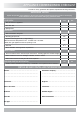
APPLIANCE COMMISSIONING CHECKLIST To assist us in any guarantee claim please complete the following information:- IMPORTANT NOTICE Explain the operation of the appliance to the end user, hand the completed instructions to them for safe keeping, as the information will be required when making any guaranteed claims. FLUE CHECK PASS FAIL 1. Flue Is correct for appliance 2. Flue flow Test 3. Spillage Test GAS CHECK 1. Gas soundness & let by test 2. Standing gas pressure mb 3.
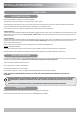
INSTALLATION INSTRUCTIONS INSTALLATION APPLIANCE LOCATION This appliance must only be fitted into a studwork installation. This appliance must not be installed in a room that contains a bath or shower. Combustible parts of the studwork must not be any closer than the minimum dimensions shown in the diagrams. NOTE: These dimensions must be maintained even if the combustible materials is protected by non-combustible linings.
INSTALLATION INSTRUCTIONS FLUE & CHIMNEY REQUIREMENTS Note: This appliance must only be installed with the flue supplied. The following: must be adhered to: The flue must be sited in accordance with BS5440: Part 1 (latest edition). Fit a guard to protect people from any terminal less than 2 metres above any access such as level ground, a balcony or above a flat roof.
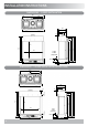
INSTALLATION INSTRUCTIONS DIMENSIONS - 3-SIDED INSTALLATION 867 434 354 342 893 214 12 10 Min 30 Max (Adjustable) 1105 1021 1040 793 906 1040 1033 700 138 Min 893 429 50 DIMENSIONS - 2-SIDED INSTALLATION (EITHER SIDE) 867 434 354 900 214 20 342 TO WALL 765 900 6 10 Min 30 Max (Adjustable) 138 Min 50 429 1105 1040 700 906 1021 1033 1040 TO WALL 12
INSTALLATION INSTRUCTIONS TECHNICAL SPECIFICATION Covering the following models: Nat Gas LPG Reflex 75T 3-Sided 191-004 191-543 Reflex 75T 2-Sided Left Facing Glass 191-010 191-414 Reflex 75T 2-Sided Right Facing Glass 191-027 191-438 Gas CAT. Gas Type Working Pressure Gas Rate m3/h Reflex 75T I2H Nat Gas G20 18mbar Reflex 75T I3+ Propane G31 37mbar Model Input kW (Gross) High Low 1.000 10.5 4.3 0.376 10.0 4.
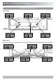
INSTALLATION INSTRUCTIONS TECHNICAL SPECIFICATION Injector Table REAR REAR Nat Gas S120 LPG S63 REAR Nat Gas S128 LPG Nat Gas S102 S78 LPG S63 Rear of appliance Front of appliance FRONT FRONT FRONT Nat Gas S92 Nat Gas S92 Nat Gas S88 LPG S60 LPG S60 LPG S60 Aeration Table NOTE: Aeration plates are on each leg of the burners. These holes are different sizes at the Front and Back for each individual leg. REAR REAR Nat Gas 5.0 (x2) LPG 7.0 (x2) Nat Gas 4.5 (x2) LPG 9.
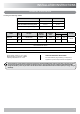
INSTALLATION INSTRUCTIONS TECHNICAL SPECIFICATION Restrictor Table RESTRICTOR REQUIREMENT - VERTICAL & HORIZONTAL FLUE SPECIFICATION Reflex 75T Vertical flue height from top of appliance Horizontal length Restrictor size 500mm - 999mm Up to 500mm N/A 1000mm - 1499mm Up to 1000mm N/A 1500mm - 3000mm Up to 5000mm N/A TOP EXIT - VERTICAL ONLY INCLUDING OFFSET Vertical flue height from top of appliance Restrictor size 1500mm - 2999mm 75mm 3000mm - 5999mm 70mm 6000mm - 10000mm 60mm PACKING CHE
INSTALLATION INSTRUCTIONS FLUE OPTIONS REAR FLUE REFLEX 75T TOP EXIT FLUE TOP FLUE UP AND OUT KIT (8523) Vertical from the top of the appliance then horizontally out. The basic kit comprises: 1 x 500mm terminal length 1 x 90 degree elbow 1 x 500mm vertical length 1 x wall plate 1 x 60mm restrictor 1 x 75mm restrictor 4 x fixing screw Terminal dimensions: 395 x 200 x 200 mm (H x W x D) Guard supplied Cut to length as required on site.
INSTALLATION INSTRUCTIONS FLUE OPTIONS TOP FLUE UP AND OUT WITH ADDITIONAL BEND REFLEX 75T - TOP FLUE VERTICAL KIT (8524) Any additional bend may be used on the horizontal section (either 45° or 90°), but the overall horizontal flue run will be reduced. This flue is vertical from the top of the appliance. A minimum vertical rise of 1.5m (4’92”) to a maximum of 10m (32’10”).
INSTALLATION INSTRUCTIONS FLUE OPTIONS REMOVING THE MOUNTING BRACKET TOP FLUE VERTICAL OFFSET KIT (8530/8530AN) This appliance weighs 108Kg. The manufacturer has designed this appliance to attach to a masonry wall and all fixings supplied reflect this. However if desired it is possible to locate the Reflex on a non-combustible studwork wall providing it is constructed to give adequate load baring support.
INSTALLATION INSTRUCTIONS MOUNTING BRACKET The fixing points must be through the timber stud and not plasterboard. Use appropriate fixings. DO NOT attach solely to a plasterboard wall.
INSTALLATION INSTRUCTIONS MOUNTING BRACKET MOUNTING BRACKET CLEARANCES Floor Mounted Combustible Material 900mm Combustible Material Combustible Material 500mm 500mm 1040 Floor Wall Mounted Side Wall 500mm Minimum 138mm From viewing area 232mm Minimum for Wall Mounted installation Floor Level 14
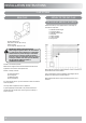
INSTALLATION INSTRUCTIONS PRE-INSTALLATION REMOVING THE GLASS 3 Top Cam Lock Brackets 1 Bottom Cam Lock Brackets 4 2 5 Top Support Bracket Gap Bottom Support Bracket Gap 6 1 2 The side glass does not need to be removed to install the appliance. It is recommended to leave the Side Glass in situ unless absolutely necessary.
INSTALLATION INSTRUCTIONS REMOVING THE MESH AND ACCESS PANEL 1 4 Centre Line Reflex 75T Rear Wall 185mm Loosen Rear Screws 289mm Silicone Panel (Approx location) Outer Box The appliance stands off the wall by 55mm. It will be necessary to build a studwork enclosure to house the mounting bracket and separate enclosures for the upper and lower faces of the appliance. Remove Front Screws WARNING: This appliance weighs 108Kg.
INSTALLATION INSTRUCTIONS Position the wall mounting bracket in the required location. 5 Run the mains power lead out of the rear of the appliance to either then left hand or right hand side. Fasten the lead with the P Clip. (Remove the clip and refit on the opposite side if required.) Wall Bracket removed for clarity 6 Once satisfied with the position of the appliance, tighten the 2 nuts on either side of the fire.
INSTALLATION INSTRUCTIONS FLUE ASSEMBLY TAKE CARE WHEN MARKING OUT FOR THE FLUE AS IT IS DIFFICULT TO MOVE AFTER INSTALLATION. IF A RESTRICTOR IS REQUIRED FIT THIS BETWEEN THE SMALL OUTLET SPIGOT AND THE AIR DUCT. REFER TO TECHNICAL SPECIFICATIONS FOR RESTRICTOR SIZE. A 152mm (6") diameter hole in the wall is required to install the flue. This can be achieved by using either: a) Core drill b) Hammer and chisel Drill small holes around the circumference when using method b).
INSTALLATION INSTRUCTIONS ENCLOSURE CONSTRUCTION 3 SIDED INSTALLATION VENTILATION Note: If the lower section of the enclosure is sealed (to the floor or capped if designed as a floating shelf) it will be necessary to provide a vent with a cut size of 300cm2 on each side. Example enclosure If the upper section is sealed (to the ceiling or capped if designed as a floating shelf) it will be necessary to provide a vent with a cut size of 300cm2 on each side.
INSTALLATION INSTRUCTIONS 3 SIDED INSTALLATION CUTTING TEMPLATES B B Upper Front Panel Side Panel x2 E A C B Lower Front Panel D A A D Inner Side Panel B C B Base Panel A A D B C Upper Inner Panel A Panel A (min) Floor Mounted Upper Front Panel Wall Mounted 1233mm Side Panel B (Min) 993mm 479mm Floor Mounted Wall Mounted C Floor Mounted D (Min) Wall Mounted 900mm - 900mm 700mm 370mm Wall Mounted - 138mm Floor Mounted Wall Mounted - 370mm 332mm Lower Front Panel 1
INSTALLATION INSTRUCTIONS 4 1 4 2 5 2 IMPORTANT: THE BASE PANEL MUST SEAL COMPLETELY TO THE SUPPORTING WALL. 6 3 1 3 NOTE: IT IS NOT NECESSARY TO SEAL THE UPPER ENCLOSURE BACK TO THE SUPPORTING WALL.
INSTALLATION INSTRUCTIONS 10 7 7 8 8 9 6 5 22
INSTALLATION INSTRUCTIONS ENCLOSURE CONSTRUCTION 2 SIDED INSTALLATION VENTILATION Note: If the lower section of the enclosure is sealed (to the floor or capped if designed as a floating shelf) it will be necessary to provide a vent with a cut size of 300cm2 on each side. Example enclosure If the upper section is sealed (to the ceiling or capped if designed as a floating shelf) it will be necessary to provide a vent with a cut size of 300cm2 on each side.
INSTALLATION INSTRUCTIONS 2 SIDED INSTALLATION CUTTING TEMPLATES A Front Side Panel B Upper Front Panel B Closed Side Panel (If not installing against a wall) A A Short Side Panel B Lower Front Panel B A A B C B F Open Side Panel Lower Base Panel D E A E D C B F C Upper Inner Panel D A Panel E A A (Min) Floor Mounted Wall Mounted B (Min) Floor Mounted Wall Mounted C (Min) Floor Mounted Wall Mounted E Wall Mounted Floor Mounted F Wall Mounted Floor Mounted Wall Mounted
INSTALLATION INSTRUCTIONS 4 1 4 5 2 IMPORTANT: THE BASE PANEL MUST SEAL COMPLETELY TO THE SUPPORTING WALL. 3 6 1 3 NOTE: IT IS NOT NECESSARY TO SEAL THE UPPER ENCLOSURE BACK TO THE SUPPORTING WALL.
INSTALLATION INSTRUCTIONS 7 10 8 11 9 26 12
INSTALLATION INSTRUCTIONS GAS SOUNDNESS PRESSURE CHECK 3 Tighten Rear Screws Connect a suitable pressure gauge to the test point located on the inlet fitting. Turn the gas supply on. Elbow Replace Front Screws NOTE: Ensure the 2 brackets at the rear are pushed as far back as possible before tightening. Remove the fixing screws and loosely place the appropriate burners onto the injectors. Light the appliance and check all gas joints for possible leaks.
INSTALLATION INSTRUCTIONS ARRANGEMENT OF FUEL BED COMPONENTS ADVICE ON HANDLING AND DISPOSAL OF FIRE CERAMICS The fuel effect and side panels in this appliance are made from Refractory Ceramic Fibre (RCF), a material which is commonly used for this application. Protective clothing is not required when handling these articles, but we recommend you follow normal hygiene rules of not smoking, eating or drinking in the work area and always wash your hands before eating or drinking.
INSTALLATION INSTRUCTIONS 5 B 3 X � ≈75 % 6 C 15mm E C 4 A 29
INSTALLATION INSTRUCTIONS 10 7 D A A D D A COMPLETION OF ASSEMBLY 8 1 2 1 THE FRONT GLASS SHOULD PRESS FIRMLY AGAINST THE SIDE GLASS 9 ≈25 % Check the alignment of all the glass panels to ensure the Front Glass and Side Glass all sit flush to one another.
INSTALLATION INSTRUCTIONS 3 Top Support Bracket 6 Gap Bottom Support Bracket Gap 4 7 5 Top Cam Lock Brackets 900 Bottom Cam Lock Brackets 900 UNDER NO CIRCUMSTANCES SHOULD THE APPLIANCE BE USED IF ANY OF THE GLASS PANELS ARE LOOSE, DAMAGED, OR MISSING. ENSURE THAT ALL GLASS PANELS ARE FLUSH AND THAT THERE ARE NO GAPS BETWEEN PANELS.
INSTALLATION INSTRUCTIONS LIGHTING THE APPLIANCE The appliance is operated by thermostatic and programmable remote control. TURNING THE APPLIANCE OFF (STANDBY) Press and hold the button to turn the appliance off. NOTE: There is a 5 second delay before the next ignition is possible. TROUBLESHOOTING IMPORTANT: In the unlikely event that the handset fails to communicate correctly with the appliance it may be necessary to turn off the gas supply at the isolation valve until any problems can be resolved.
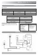
INSTALLATION INSTRUCTIONS Connect the module lead to the Wi-Fi module. 5 2 Wi-Fi Router Smart Device LED's Interrupter Leads Ignition Cable AUX Lead Lighting Module Position the Wi-Fi module in the Wi-Fi module bracket. 3 Valve Lead Wall Switch Lead (not applicable) Mains Lead Wi-Fi Module Connecting Wire NOTE: Ensure none of the wires are snagged or caught on any internal components.
INSTALLATION INSTRUCTIONS MYFIRE WI-FI SET UP & TROUBLESHOOTING It may be necessary to reset the MyFire Wi-Fi box using a paperclip or similar. The table below shows the length of time required for each reset and the confirmation signals. The MyFire Wi-Fi box must be wired according to the MyFire set up diagram and connected to the receiver, which is in turn connected to the mains power.
INSTALLATION INSTRUCTIONS COMMISSIONING Complete the Commissioning Checklist at the front of this manual covering: — Thermocouple soundness checks. This is to include ensuring the thermocouple is secure on the pilot bracket assembly, lead connection and integrity. — Flue checks — Gas checks — Log layout - flame picture REPROGRAMMING HANDSET/ CONTROL BOX To access the control box: Remove the decorative trim, see Servicing Instructions.
SERVICING INSTRUCTIONS SERVICING/FAULT FINDING CHARTS SERVICING REQUIREMENTS IMPORTANT – The glass panels on this appliance should be checked for any signs of damage on the front face of the glass panel (scratches, scores, cracks or other surface defects). If damage is observed, the glass panel must be replaced and the appliance must not be used until a replacement is installed. Under no circumstances should the appliance be used if any damage is observed.
SERVICING INSTRUCTIONS FAULT FINDING CHARTS IGNITION FUNCTIONAL CHECK 1 PILOT WILL NOT LIGHT Ensure there is no debris around the pilot assembly, (e.g. soot, etc.) which could short the spark, clean the area. No Operate the valve control system in the manual mode via the remote. Is there a spark? Consult User Instructions and retry. Yes Yes Does the pilot light? No No Is the control being operated correctly? Yes Ensure gap between the electrode and pilot burner is 4.0mm and retry.
Replace the lead, retry. No Has the ignition lead become detached from the control box? No Yes No No Correct and retry. Check Gap Is the control system being operated correctly? Check handset batteries are OK. Replace if required. Check handset is on manual. Check if handset lock is off. Replace the ignition lead and retry. Yes Remove the ignition lead from electrode. With insulated pliers.
SERVICING INSTRUCTIONS GENERAL All main components can be replaced without removing the appliance from its installation. Repeat for the 2 upper Brackets and 2 lower Brackets. 62 Upper Side Brackets DISCONNECT MAINS ELECTRICAL SUPPLY AT THE ACCESSIBLE PLUG OR DEDICATED SWITCH BEFORE SERVICING THE APPLIANCE. IT IS ESSENTIAL THAT THE GAS SUPPLY TO THE APPLIANCE IS TURNED OFF AT THE ISOLATION DEVICE BEFORE PROCEEDING FURTHER.
SERVICING INSTRUCTIONS 5 2 Top Support Bracket Gap Bottom Support Bracket Gap 6 1 3 2 Top Cam Lock Brackets Bottom Cam Lock Brackets The side glass does not need to be removed to install the appliance. It is recommended to leave the Side Glass in situ unless absolutely necessary. The glass panel must be refitted to the appliance following cleaning or servicing. To replace the glass panel, replace in reverse order.
SERVICING INSTRUCTIONS REMOVING THE LOG BURNERS AND MAIN CONTROL ASSEMBLY REMOVING THE FUEL EFFECT The fuel effect consists of 12 different components: — 5 Logs — 3 Large embers — 2 Small embers — Shale effect & amber effect To avoid damage Logs A, B, C and D should be removed in the following order and placed on a dry, clean surface. Remove the Front Glass. Remove the Fuel Effect. 1 Remove Logs D, B and C. B D C 2 Slide Log A backwards, from under the centre Log Burner, to remove.
SERVICING INSTRUCTIONS 4 REPLACING THE LED CIRCUIT There are 3 LED boards, which can be replaced individually. Screws Driver Front LED 1 Rear LED bar Front LED 2 Turn the gas supply off at the isolation device. HAVE YOU ISOLATED THE GAS SUPPLY? Disconnect the isolating device from the appliance inlet pipe (A) to isolate the gas supply. THE LED'S ARE FRAGILE. HANDLE WITH CARE. ONLY HOLD THE LED BOARDS BY THE EDGES TO AVOID CONTACT WITH THE TOP OF THE LED'S.
SERVICING INSTRUCTIONS 6 2 Screw Withdraw the module and disconnect the LED Mains Lead Plug. 3 The boards can now be replaced. NOTE: Each board has the wiring direction marked as IN or OUT on each end to ensure the replacement boards are wired correctly. Rear LED bar Remove the Main Control Assembly. Remove the 2 screws securing the LED cradle to the underside of the Control Assembly. 7 LED Lead Plug 4 Screw Screw 8 Wires 5 9 Replace in reverse order.
SERVICING INSTRUCTIONS The pilot assembly consists of three components, which can be individually changed, these are: REPLACING THE MODULE Remove the magnetic trims, and the lower Glass Support Bracket. Remove the module cover and disconnect the LED plug and Mains Lead from the Module. Mains Lead Electrode. Pilot Injector. Thermocouple. Thermocouple Electrode Pilot Injector Screws Ignition Lead Pilot Pipe Module Lead LED Plug Disconnect the Module Lead.
SERVICING INSTRUCTIONS IGNITION LEAD MAGNETIC SAFETY VALVE Unplug the Ignition lead from the control box. Remove the Log Burners and Main Control Assembly. Undo the Thermocouple from the Interrupter Block and remove the 2 Interrupter Leads. Unscrew the Interrupter Block from the back of the Valve. Undo the silver Magnetic Valve retaining nut on the back of the Valve. Gently tap out the Mag Valve. Replace with a new unit.
SERVICING INSTRUCTIONS Remove the 8 way cable from the Control Box. FUEL BED INJECTORS 8 Way Cable Interrupter Leads Solenoid Control Box This appliance has 6 Fuel Bed Injectors. NOTE: The injectors are not identical, see Page 8. TO ENSURE CORRECT ASSEMBLY REPLACE EACH INJECTOR INDIVIDUALLY. Remove the Magnetic Trim, Front Glass, Log Burners and Mesh Tray. Solenoid Lead Module Lead Remove the 2 nuts and lock washers from each Burner Bracket.
SERVICING INSTRUCTIONS CROSS LIGHTING INJECTOR LATCHING SOLENOID Remove the Magnetic Trim, Front Glass, Log Burners and Main Control Assembly Remove the Magnetic Trim, Front Glass, and Main Control Assembly. Turn the Main Control Assembly over to access the components on the underside. Remove the cradle holding the rear LEDs to access the pipe work for the solenoid. Remove the injector pipe by loosening the two nuts. Undo the three nuts shown and free the solenoid from the pipework.
SERVICING INSTRUCTIONS 2-SIDED MODELS LINERS Remove the Front Glass, Fuel Effect, and Main burners. 3-SIDED MODELS The following instructions assume a right-handed installation. If fitting a left-handed installation the instructions are still correct, however, the images may not wholly reflect the installation in question. If fitted, remove the decorative trims. channels. 1 1 2 2 1 2 3 1 3 2 To replace the Liners reverse these procedures.
SERVICING INSTRUCTIONS 5 Underside of Baffle Front of appliance 1 2 To replace the Liners reverse these procedures. Ensure no amber glass or black shale has fallen onto the side liner infill or liner support brackets. 2 To Replace the Side Glass: Place the Side Glass panel in position. Do not tighten the brackets at this stage. Replace the Front Glass Panel and tighten the front brackets, ensuring the Side Glass sits on the spring clip located in the rear channel.
SERVICING INSTRUCTIONS 2 REPLACING THE POWER CABLE Upper Side Brackets BEFORE UNDERTAKING ANY WORK SWITCH OFF THE APPLIANCE AND ISOLATE THE POWER SUPPLY ENSURING THERE IS NO POWER TO THE APPLIANCE. To replace the Power Cable first remove the Main Control Assembly. Lower Side Brackets Disconnect the 3 cables from the Power Module, Arrow A. NOTE THE CONFIGURATION OF THE WIRES. B 3 A 1. 2. 3. Remove the nuts from the Earth stud and remove the two Ring Terminals, Arrow B.
SPARES LIST REFLEX 75T MAIN ASSEMBLY - 3-SIDED No. Component Part Code Natural Gas LPG Qty. No. Component Part Code Natural Gas LPG Qty.
SPARES LIST REFLEX 75T MAIN ASSEMBLY - 2-SIDED No. 1 Component Ceramic Log Set Part Code Natural Gas LPG CE1731 Part Code Qty. No. 1 20 Hand Tool GZ15428 1 Component Natural Gas LPG Qty.
SPARES LIST REFLEX 75T CONTROL ASSEMBLY No. Component Part Code Natural Gas LPG Qty. No. Component Part Code Natural Gas 1 Latching Solenoid Valve EL0563 1 15 Power Module Box EL0672 2 Ignition Cable GC0125 1 16 M8x1 Fine Thread Brass Locknut FA0740 3 Thermo Current Cable GC0126 1 17 Cross Lighting Injector IN0092 LPG Qty.
INFORMATION REQUIREMENT - GAS HEATERS Reflex 75T Multi-sided BF NG Reflex 75T Multi-sided BF LPG INFORMATION REQUIREMENT FOR GASEOUS FUEL LOCAL SPACE HEATER 130 130 Nominal Heat Output - Pnom 8.7kW 8.5kW Minimum Heat Output (indicative) -Pmin 3.0kW 3.0kW At Nominal Heat Output - elmax 0.003kW 0.003kW At Minimum Heat Output - elmin 0.003kW 0.003kW In Standby Mode - elsb 0.003kW 0.003kW Useful Efficiency at nominal heat output - ηth,nom 92.0% 92.
SERVICE RECORDS 1ST SERVICE 2ND SERVICE Date of Service:.......................................................................... Date of Service:.......................................................................... Next Service Due:...................................................................... Next Service Due:...................................................................... Signed:....................................................................................... Signed:.....
Gazco Limited, Osprey Road, Sowton Industrial Estate, Exeter, Devon, England EX2 7JG Technical Customer Services: (01392) 261950 Fax: (01392) 261951 E-mail: technicalservices@gazco.