
Logic HE Balanced Flue Combined Controls Installation User Instructions


20
Installation Instructions
4.5 Do not pack the void around or above the appliance with
insulation material such as mineral wool.
5
4.6 The void into which the appliance is fitted must be
ventilated to prevent a build up of heat. If the void is sealed
then it will be necessary to fit vents at both low and high
levels of approximately 50cm
2
. These vents should take
cold air from the room and return warm air back into the
room.
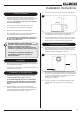
5. Recessed Installation
This method of installation requires structural alteration to
the intended location. A suitable supporting lintel must be
installed to maintain the structural integrity of the
surrounding blockwork.
5.1 Mark the position of the lintel so that it sits centrally over
the intended installation. Remove the blockwork and install
the lintel using mortar to ensure a strong bond with the
surrounding wall, see Diagram 6.
6
5.2 With the lintel in position mark the width of the aperture
and remove the blockwork.
5.3 Seal the cavity with non combustible board, to prevent any
insulation touching the appliance.
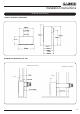
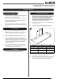
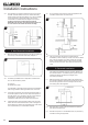
3.4 The appliance can either be recessed into an inner leaf of
the wall. A 20mm rebated surround or 20mm thick back
panel must be used with this method. Or it can be installed
in front of the wall in conjunction with a fire surround
constructed of a studwork frame, Diagram 3 for options.
If using a back panel constructed from natural
materials such as stone, the panel should consist of 3
or more sections to reduce the risk of cracking.
160mm
20mm
3
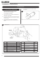
4. Non Recessed Installation
4.1 Mark the position of the flue on the inner wall by measuring
from the top of the finished hearth level, Diagram 4.
4
4.2 A 152mm (6’) diameter hole is required to install the flue.
This can be achieved by either:
a) Core drill
b) Hammer and chisel.
It is advisable to drill small holes around the circumference
when using method b. Make good both ends of the hole.
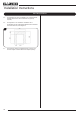
4.3 It will now be necessary to construct a studwork frame to
house the appliance. The minimum depth of the aperture
must be 165mm. This includes an air gap of 5mm behind
the appliance. The sides must be lined with non-
combustible material for the full depth of the aperture.
4.4 Combustible parts of the studwork frame must not be any
closer than the minimum dimensions shown in Diagram 5.
These dimensions need to be maintained even if the frame
work is protected by non combustible material.