
Logic HE Balanced Flue Combined Controls Installation User Instructions

21
Installation Instructions
5.4 Ensure that there is a minimum of 10mm gap left between
the back of the appliance and the outer wall. There must
be no combustible materials behind this appliance.
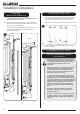
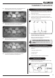
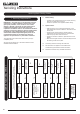
5.5 Mark the position of the flue on the wall by measuring from
the top of the finished hearth level, see Diagram 7.
7
5.6 A 152mm (6’) diameter hole is required to install the flue.
This can be achieved by either:
a) Core drill
b) Hammer and chisel
It is advisable to drill small holes around the circumference
when using method b. Make good both ends of the hole.
6. Installation of the Appliance
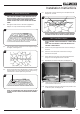
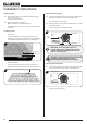
6.1 The flue can be cut to length, measure the thickness of the
wall the flue is passing through, then deduct 12mm. This is
the length required when measuring from the line on the
flue label. This must be level with the outside wall face
when fitted, see Diagram 8.
8
6.2 There is a cardboard fitment in the terminal. This is to
support the flue whilst it is cut to length. REMOVE THE
REMAINDER OF THE CARDBOARD AFTER CUTTING
TO SIZE.
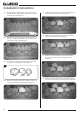
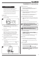
6.3 Remove the compression elbow from the appliance and
connect it to the gas supply pipe, taking note of its
orientation.
NOTE: TO AID INSTALLATION OF THE GAS PIPE, THE
BURNER UNIT CAN BE REMOVED. SEE REPLACING
PARTS, SECTION 2.
6.4 Attach the flue to the appliance and seal using the
aluminium tape provided.
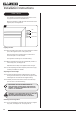
6.5 As the appliance is positioned into the opening of the
enclosure, pass the flue pipe through the hole in the wall. It
will be necessary to pass the supply pipe with the elbow
through the silicone panel on the right hand side of the box.
6.6 Secure the appliance in place using screws and rawl plugs
provided.
6.7 PURGE THE SUPPLY PIPE. This is essential to expel any
debris that may block the gas controls. Connect the elbow
to the appliance inlet pipe.
6.8 Connect a suitable pressure gauge to the test point located
on the inlet elbow and turn the gas on.
6.9 Light the appliance and check for leaks.
6.10 Turn the appliance to maximum and check that the supply
pressure is as stated on the databadge.
6.11 Turn the gas supply off and replace the test point screw.
Turn the gas on and check the test point for leaks.