Logic HE™ Range Conventional Flue Instructions for Use, Installation and Servicing For use in GB, IE (Great Britain and Republic of Ireland) IMPORTANT THE OUTER CASING, FRONT AND GLASS PANEL BECOME EXTREMELY HOT DURING OPERATION AND WILL RESULT IN SERIOUS INJURY AND BURNS IF TOUCHED. IT IS THEREFORE RECOMMENDED THAT A FIREGUARD COMPLYING WITH BS 8423 (LATEST EDITION) IS USED IN THE PRESENCE OF YOUNG CHILDREN, THE ELDERLY OR INFIRM. This product contains a Heat resistant glass panel.
Contents Logic HE Conventional Flue Covering the following models: Gas Type Logic He Cf Manual Control Remote Control Slide Control Coal White Stones Coal White Stones Coal White Stones Nat Gas 101-151 101-324 101-088 101-131 101-037 101-110 LPG 101-497 101-651 101-614 101-649 101-444 101-597 Appliance Commissioning Checklist.......................3 User Instructions........................................................4 Installation Instructions.................................
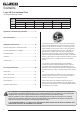
Appliance Commissioning Checklist To assist us in any guarantee claim please complete the following information:- IMPORTANT NOTICE Explain the operation of the appliance to the end user, hand the completed instructions to them for safe keeping, as the information will be required when making any guaranteed claims. FLUE CHECK PASS FAIL 1. Flue Is correct for appliance 2. Flue flow Test 3. Spillage Test GAS CHECK 1. Gas soundness & let by test 2. Standing gas pressure mb 3.
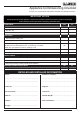
User Instructions Welcome Congratulations on purchasing your Logic HE fire, if installed correctly Gazco hope it will give you many years of warmth and pleasure for which it was designed. The purpose of this manual is to familiarise you with your appliance, and give guidelines for its installation, operation and maintenance. If, after reading, you need further information, please do not hesitate to contact your Gazco retailer. WARNING 1.
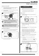
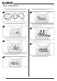
User Instructions Adjusting the Flame height 2.5 From the pilot position push the valve knob in slightly and rotate anti-clockwise until the first stop point is felt. This denotes the lowest setting. 2.6 Push the valve knob in slightly and rotate further in an anticlockwise direction. The final stop point is the highest setting. 2 Off position Pilot position Remote Control The control valve is at the foot on the right-hand side of the appliance. It has two controls, see Diagram 4: 1.
User Instructions To light the main burner: 2.14 Slide Control Press buttons A & B simultaneously. The remote’s LED light flashes to show communication between the appliance's controls and the remote. This appliance is operated using the slide control on the top right hand side of the decorative front. When the appliance is OFF the slide control will be at the highest point, see Diagram 6. Adjusting the Flame height: 2.15 Press and hold buttons A & B simultaneously to increase the flame height.
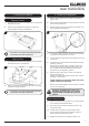
User Instructions 4. Cleaning the Appliance 3. Changing the Battery Remote Control 4.1 Make sure the appliance and surrounds are cool before trying to clean. 3.1 The battery box is located at the bottom left of the appliance behind the ash cover. 4.2 Refer to the separate decorative front instructions to remove the front from the appliance. 3.2 Remove the old batteries and replace with a new high quality (Duracell or similar) 4 AA batteries. 4.
User Instructions Coal Effect 4.12 Remove the ceramic coals and fuel bed and place on a dry clean surface. 4.13 Check the burner cover gasket for damage. Replace any damaged parts with genuine Gazco replacement parts, contact your Gazco retailer. 4.14 Carefully clean the burner and tray assembly using a vacuum cleaner with soft brush attachment, ensure all debris is removed from the burner ports. 5A. White Stone Layout ONLY USE THE CORRECT TYPE AND QUANTITY OF WHITE STONES.
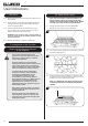
User Instructions 5.4 Ensure that no stones overhang or fill the pilot area, see Diagram 13, Arrow B. NOTE: STONES SHOULD NOT BE PLACED DIRECTLY IN FRONT OF THE PILOT CROSS LIGHTING FLAME. 5.9 Repeat with the second side panel, see Diagram 15. 15 13 B 5B. Coal Effect Layout NOTE: CERAMIC PARTS ARE FRAGILE. HANDLE WITH CARE. 5.10 Locate the top panel on top of the sides and rear by lifting it up and forward inside the box. 5.
User Instructions 5.14 There are three sizes of coal used: 3 x Large, 4 x Small and 1 x Half Moon shaped. For identification, see Diagram 19. 19 Place a small coal directly behind the first large coal, and rest it on the flame baffle, see Diagram 23. 23 LARGE 5.15 5.18 SMALL HALF MOON Place a single large coal in the right hand dent of the front coal resting against the flame baffle, see Diagram 20. 5.19 20 24 Place two of the remaining small coals in the spaces next to the first.
User Instructions 12. Hot Surfaces 6. Oxygen Depletion Sensor The appliance is fitted with an oxygen sensitive pilot system that will act to cut off the gas supply to the appliance should the oxygen in the room fall below its normal level. If the appliance is turned off by this device, it usually indicates that there is a problem with the flue system, and this should be inspected by a qualified engineer. Do not attempt to use the appliance until an engineer says it is safe to do so.
Installation Instructions Technical Specification - Stone Effect Covering the following models: Model Gas Type Logic HE Stone Effect Manual Control Remote Control Nat Gas 101-324 101-131 101-110 LPG 101-651 101-649 101-597 Gas Cat. Gas Type Working Pressure Aeration Injector I2H Natural G20 20mb 6mm x 6mm I3P Propane G31 37mb 12mm x 15mm Slide Control Gas Rate m3/hr Input kW (Gross) Country High Low High Low 240 0.390 0.238 4.1 2.5 GB, IE 102 0.162 0.090 4.3 2.
Installation Instructions Technical Specification - Coal Effect Covering the following models: Model Logic HE Coal Effect Gas Type Manual Control Remote Control Slide Control Nat Gas 101-151 101-088 101-037 LPG 101-497 101-614 101-444 Gas Cat. Gas Type Working Pressure Aeration Injector I2H Natural G20 20mb 5 x 16 063 Gas Rate m3/hr Input kW (Gross) High Low High Low 0.486 0.238 5.1 2.5 0.181 0.090 4.8 2.4 0.181 0.090 4.8 2.4 0.184 0.090 4.9 2.
Installation Instructions Technical Specification Complete Front Options FRONT Manual & Remote Slide Control 912-396, 912-018 - DESIGNIO 2 901-493, 901-511, 901-526 901-539, 901-580, 901-643 EVOLUTION 912-601 - FUTURA 8687BK - FUSION 8699GP + 8699IR - 912-239 - 912-197, 912-221, 912-316 901-385, 901-403, 901-414 WINCHESTER 8697MB + 8697P 901-369, 901-372 DIMENSION2 912-322 - 8695GP + 8695IR - RICHMOND * 8679 - STOCKTON * 8696 - YM98906 - DESIGNIO PROGRESS TEMPO STEEL *
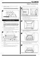
Installation Instructions Technical Specification 1 190 125 372 550 OVERALL EXTERNAL DIMENSIONS SIDE VIEW 2 MINIMUM 50MM 125MM MINIMUM DEBRIS COLLECTION SPACE REQUIREMENTS (EXISTING MASONRY CHIMNEYS ONLY) 3 404 186 OVERALL EXTERNAL DIMENSIONS PLAN VIEW 483 15
Installation Instructions Site Requirements 1. Flue & Chimney Requirements 1.1 The chimney or flue system must comply with the rules in force, and must be a minimum of 125mm (5”) in diameter. Precast flues must conform to BS1289: 1986. The cross sectional area of the flue must be 16500mm2 with a minimum dimension of 90mm. 1.2 2 When fitting the appliance to a precast flue, the total minimum depth of appliance opening necessary is (D) 215mm.
Installation Instructions Site Requirements 2.8 2. Appliance Location 2.1 2.2 2.3 This appliance must stand on a non combustible hearth that is at least 12mm thick. If the appliance is greater than 50mm above the floor, then no hearth is required, although due consideration should be given to how the heat may affect the floor material. NOTE: It is recommended you construct the back panel of the fireplace from natural materials cut into three or more sections to prevent cracking.
Installation Instructions 1. Safety Precautions 1.1 For specific gas types and working pressures see Technical Specifications, pages 12 and 13. For your own and other’s safety, you must install this appliance according to local and national codes of practice. Failure to install the appliance correctly could lead to prosecution. Read these instructions before installing and using this appliance. 1.2 These instructions must be left intact with the user. 1.
Installation Instructions Manual Control 3.3 Remove the 5 burner retaining screws and withdraw the burner unit from its location, see Diagram 2. NOTE: IF REMOVING THE BURNER, IT WILL BE NECESSARY TO REMOVE THE DECORATIVE INNER PANEL, SEE SECTION 5. 3.6 Remove the M4 lock nut and spacer securing the slider arm to the appliance, see Diagram 5. Ensure that the spacer is retained and replaced when the engine is reinstalled. 5 2 M4 Lock Nut and spacer Withdraw the burner unit from its location.
Installation Instructions 4. Installation of the Appliance 4.1 Ensure that the fireplace opening is in compliance with Section 2 Site Requirements then proceed as follows: A) Cable Retention Method 4.2 4.6 Slide the locking nipples onto the cables, pull the cables taut and tighten the locking screw. Adjust the lock nuts using a 10mm spanner until the silicone sealing strip forms a tight seal between the fireplace opening and the firebox flange, see Diagram 10.
Installation Instructions 4.12 Connect the gas supply to the inlet connection on the burner unit and tighten. It may be necessary to support the inlet connection with another spanner whilst tightening this joint, see Diagram 12. 12 Manual Model shown Foam Seal (Slide Control Models only) The foam seal must be fitted to the appliance prior to attaching the decorative front. 4.
Installation Instructions 5. Fitting the Decorative Inner Panel - White Stone Effect 5.1 6. Arrangement of the Fuel Bed Advice on handling and disposal of fire ceramics By rotating the panel, insert into firebox, see Diagram 15. 15 The fuel effect and side panels of this appliance are made from Refractory Ceramic Fibre (RCF), a material which is commonly used for this application.
Installation Instructions 6.2 Lean the white stones against the burner ledges to disguise the ledges, see Diagram 19. 6B. Coal Effect Layout NOTE: CERAMIC PARTS ARE FRAGILE. HANDLE WITH CARE. 19 ONLY USE THE CORRECT TYPE AND QUANTITY OF CERAMIC COMPONENTS. ALWAYS FOLLOW THE FUEL BED LAYOUT AS STATED IN THESE INSTRUCTIONS. NEVER CHANGE THE LAYOUT FROM THAT SHOWN HERE. 6.5 6.3 Check that the port area, see Diagram 20, Arrow A is clear of white stones.
Installation Instructions 6.11 Slide it backwards and down behind the side panels to rest on the rear panel, see Diagram 24. 6.15 28 24 6.16 6.12 Place a single large coal in the right hand dent of the front coal resting against the flame baffle, see Diagram 28. Position the flame baffle centrally on the tray and ensure the stepped lower edge engages against the rear edge of the burner skin, see Diagram 25.
Installation Instructions 6.19 32 Place two of the remaining small coals in the spaces next to the first. The final small coal sits at the front right next to the large coals, see Diagram 32. 1 UNDER NO CIRCUMSTANCES SHOULD THE APPLIANCE BE USED IF ANY OF THE GLASS FRAME RETAINING SCREWS ARE LOOSE OR MISSING. 2 8. Operating the Appliance 8.1 There are three types of control systems available for this appliance: 1. Manually Operated Control 3 2. Remote Control 3. Slide Control 6.
Installation Instructions YELLOW FLAMES APPEAR WHEN THE APPLIANCE HAS REACHED SUFFICIENT HEAT – (10 TO 20 MINUTES). IF THE APPLIANCE IS EXTINGUISHED OR GOES OUT IN USE, WAIT 3 MINUTES BEFORE TRYING TO RELIGHT. 8.12 Turn the right-hand control to point to main burner ( ). The appliance can now be controlled by the remote handset. 8.13 The Standard remote controls the appliance when: Switching OFF the Appliance 8.7 37 — the pilot is lit. — the right-hand control points to main burner operate position.
Installation Instructions Remote Control Adjusting the Flame height 8.20 8.25 Increase the flame height and temperature by carefully moving the slide control up until the next stop point is felt, see Diagram 40. This denotes the highest setting. 8.26 Carefully move the slide control down to the lower stop point to return to the lowest setting. To turn the main burner of the appliance off using the handset press and keep pressing the Off button ( ).
Commissioning 1. Commissioning 1.1 Close all windows and doors to the room, check all controls, and allow appliance to burn on maximum for 5 minutes. Test for spillage of flue products using a smoke match. Pass the lighted smoke match along the top front of the draught diverter, just inside, see Diagram 1. 1 1.2 If the appliance spills, run for a further 10 minutes and re-check. 1.3 Complete the Commissioning Checklist at the front of this manual covering: — Thermocouple soundness checks.
Servicing Instructions Servicing/Fault Finding Charts Before Testing: 1.1 1. Servicing Requirements — Conduct a gas soundness test for the property ensuring there are no leaks before servicing. — Check the operation of the appliance before testing. IMPORTANT – The glass panel on this appliance should be checked for any signs of damage on the front face of the glass panel (scratches, scores, cracks or other surface defects).
Yes Replace the ODS unit Yes Is the ignition lead detached from the piezo in the valve? No Remove the ignition lead from electrode with insulated pliers hold the tip 3.
Servicing Instructions Fault Finding Charts FLAME FAILURE FUNCTIONAL CHECK 3 PILOT WILL NOT STAY LIT OR APPLIANCE GOES OUT If the appliance goes out in use continually, this may mean that the oxygen depletion sensor has been activated. The appliance should not be used until the cause has been found and rectified. Ensure there is no debris around the pilot assembly, e.g. coal, soot, etc. Check for fluff in the pilot aeration hole.
Servicing Instructions - Replacing Parts Coal Effect Only 1. Servicing As part of the annual service, the space behind the firebox must be inspected for any debris, which may have fallen down the chimney. 1.1 To remove the main burner from the firebox first remove the decorative front. There are 2 screws securing the front to the appliance. Refer to separate instructions. 1.2 Turn off the gas supply at the isolation device located under the appliance. 1.
Servicing Instructions - Replacing Parts Slide Control 1.17 White Stone Effect Only Remove the battery before carrying out work on this appliance. The battery box is located at the bottom left of the appliance behind the ash cover, see Diagram 4. 4 1.18 9V Battery 1.22 Remove the white stones and place on a clean dry surface. 1.23 Remove the two decorative panel securing clamps, see Diagram 7. 7 Ignition Unit Remove the 6 screws securing the burner unit to the firebox, see Diagram 5. 1.
Servicing Instructions - Replacing Parts 3.5 2. General 2.1 To service any of the following parts of the appliance, it will be necessary to remove the burner unit from the firebox. To remove the burner refer to Servicing Section 1. 2.2 The heat shield needs to be removed from the burner for servicing. To do this remove the three screws indicated in Diagram 9 and slide the shield forward. 9 Remove the clip from around the front of the valve, see Diagram 11.
Servicing Instructions - Replacing Parts 3.12 To release the right hand side of the control cover insert the narrow blade screwdriver into the slot shown in Diagram 14, lever it gently and pull from the right hand side at the same time. The cover will now come off, there is a small cylindrical metal spacer inside the cover, this must be kept and replaced on the fixing screw during re-assembly. 4.
Servicing Instructions - Replacing Parts 5.2 Lift the shroud up and away from the pilot unit. Manual Control & Remote Control 18 5.8 Undo the thermocouple connection at the back of the gas valve and the pilot pipe at the pilot unit, see Diagrams 21 or 22, Arrows B and C. 21 5.3 Manual Control Remove the 2 screws securing the pilot assembly, see Diagram 19, Arrow C. 19 C C B 22 5.4 Remote Control C Replace the pilot assembly, see 5.13. Coal Effect 5.
Servicing Instructions - Replacing Parts 6.5 All Models 5.13 Replace with a new pilot assembly and check the spark gap, see Diagram 24. Disconnect the injector nut, see Diagram 26, Arrow E. 26 24 E 5.14 After reassembly check for gas soundness and carry out a flame failure functional check as detailed in the Fault Finding chart, especially the time it takes for the mag unit to close. 6. Gas Valve Undo the 2 bolts securing the gas valve to the appliance and remove the valve unit. 6.
Servicing Instructions - Replacing Parts 6.25 Slide Control 6.18 To remove the gas valve first remove the thermocouple, see Diagram 28, Arrow A. Remove the front channel from the top of the burner unit by undoing the 2 screws, see Diagram 31. Note: When replacing the front channel ensure that the end with the 2 holes is located to the right side of the burner unit with the taller face to the front. 31 28 C D B Screws A 6.19 Undo the pilot pipe from the gas valve, see Diagram 28, Arrow B. 6.
Servicing Instructions - Replacing Parts 7. Mag Unit 8. Main Injector 7.1 Undo the thermocouple nut, see Diagram 34, 35 or 36, Arrow B. 34 Manual Control 8.1 Undo the injector compression nut and valve nut, see Diagram 37, 38 or 39, Arrows D and E, and pull the pipe clear of the injector body. 37 Manual Control E D B 35 Remote Control Remote Control 38 E D B 36 Slide Control 39 Slide Control D E B 7.
Servicing Instructions - Replacing Parts Slide Control: 9. Ignition Unit (Slide Control Model only) PART 9.1 Remove the battery, see Section 1. 9.2 Remove the 2 leads and the pilot ignition lead from the ignition unit, see Diagram 40. 40 Pilot Ignition Lead Screw (Behind unit) Screw 9.3 Undo the 2 screws securing the unit in place, see Diagram 40. 9.4 Replace in reverse order. 10.
Servicing Instructions - Replacing Parts 11a. Spares List - Manual Control - Coal No.
Servicing Instructions - Replacing Parts 11a. Spares List - Manual Control - Coal - Burner Assembly No.
Servicing Instructions - Replacing Parts 11a. Spares List - Manual Control - Stone No. Component Part Code Natural Gas LPG Quantity ME11518 ME11519 1 1 Restrictor Plate 2 Silicon Seal FA0354 1 3 Gasket Plate ME3746 1 4 Instruction Manual & Fixing Kit GZ9179 1 5 White Ceramic Stones 1.
Servicing Instructions - Replacing Parts 11a. Spares List - Manual Control - Stone - Burner Assembly No.
Servicing Instructions - Replacing Parts 11b. Spares List - Remote Control - Coal No.
Servicing Instructions - Replacing Parts 11b. Spares List - Remote Control - Coal - Main Burner Assembly No.
Servicing Instructions - Replacing Parts 11b. Spares List - Remote Control - Stone - Main Burner Assembly No. Component Part Code Natural Gas LPG Quantity ME11518 ME11519 1 1 Restrictor Plate 2 Silicon Seal FA0254 1 3 Gasket Plate ME3746 1 4 Instruction Manual & Fixing Kit GZ10078 1 5 White Ceramic Stones 1.
Servicing Instructions - Replacing Parts 11b. Spares List - Remote Control - Stone - Main Burner Assembly No.
Servicing Instructions - Replacing Parts 11b. Spare Parts List - Remote Control - Control Assembly No.
Servicing Instructions - Replacing Parts 11c. Spares List - Slide Control - Coal No. 1 Component Restrictor Plate 2 M4 x 6 Pozi Drive Screw 3 Spring Clip 4 M4 x 10 Cross CSK HD Screw 5 6 7 Part Code No.
Servicing Instructions - Replacing Parts 11c. Spares List - Slide Control - Coal - Main Burner Assembly No. Component 1 Burner Tray 2 Burner Skin Gasket 3 Burner Gasket Bracket 4 Pilot 5 Restricter Elbow 6 Burner Plate 7 Screw M4 x 12mm 8 Washer Part Code Natural Gas LPG GZ4462 Quantity No.
Servicing Instructions - Replacing Parts 11c. Spares List - Slide Control - Stone No. Component 1 Restrictor Plate 2 M4 x 6 Pozi Drive Screw 3 Spring Clip 4 M4 x 10 Cross CSK HD Screw 5 6 7 Part Code Natural Gas LPG Quantity No.
Servicing Instructions - Replacing Parts 11c. Spares List - Slide Control - Stone - Main Burner Assembly No.
Service Records 1ST SERVICE 2ND SERVICE Date of Service.......................................................................... Date of Service........................................................................ Next Service Due....................................................................... Next Service Due..................................................................... Signed........................................................................................ Signed............
Information Requirement - Gas Heaters Logic HE CF Manual Control NG Coal Logic HE CF Manual Control LPG Coal Logic HE CF Manual Control NG Stones Logic HE CF Manual Control LPG Stones 130 130 130 130 Nominal Heat Output - Pnom 4.1kW 4.0kW 3.3kW 3.5kW Minimum Heat Output (indicative) - Pmin 1.8kW 1.7kW 1.8kW 1.
Information Requirement - Gas Heaters Logic HE CF Remote Control NG Coal Logic HE CF Remote Control LPG Coal Logic HE CF Remote Control NG Stones Logic HE CF Remote Control LPG Stones 130 130 130 130 Nominal Heat Output - Pnom 4.1kW 3.9kW 3.3kW 3.5kW Minimum Heat Output (indicative) - Pmin 1.8kW 1.7kW 1.8kW 1.
Information Requirement - Gas Heaters Logic HE CF Slide Control NG Coal Logic HE CF Slide Control LPG Coal Logic HE CF Slide Control NG Stones Logic HE CF Slide Control LPG Stones 130 130 130 130 Nominal Heat Output - Pnom 4.1kW 3.9kW 3.3kW 3.3kW Minimum Heat Output (indicative) - Pmin 1.8kW 1.7kW 1.8kW 1.
Gazco Limited, Osprey Road, Sowton Industrial Estate, Exeter, Devon, England EX2 7JG Technical Customer Services: (01392) 261950 Fax: (01392) 261951 E-mail: technicalservices@gazco.