
Logic HE Conventional Flue Combined Controls Installation User Instructions

25
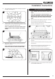
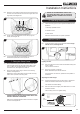
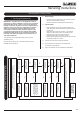
6.19 Place two of the remaining small coals in the spaces next to
the first. The final small coal sits at the front right next to the
large coals, see Diagram 32.
1
2
3
32
6.20 Finally position the Half Moon coal on the top right as
shown, see Diagram 33.
33
6.21 It is essential that gaps are left between the coals to
maximise the performance of the appliance.
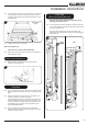
7. Fitting the Glass Frame
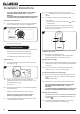
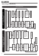
7.1 Ensure that the fibre glass seal on the box is intact, then
lower the glass frame into the lower location tabs on the
box. The tabs should locate between the glass and the
decorative front, see Diagram 34, Detail A.
7.2 Secure the glass frame using 4 screws in the retaining
bracket, see Diagram 34.
Replace ALL of the glass frame securing screws ensuring
that a screw is present in all fixing slots.
Detail A
A
34
NEVER OPERATE THE APPLIANCE WHEN THE GLASS
FRAME IS REMOVED OR BROKEN.
Refer to the separate decorative front Instructions to replace
the front on the appliance.
UNDER NO CIRCUMSTANCES SHOULD THE
APPLIANCE BE USED IF ANY OF THE GLASS
FRAME RETAINING SCREWS ARE LOOSE OR
MISSING.
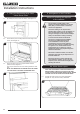
8. Operating the Appliance
8.1 There are three types of control systems available for this
appliance:
1. Manually Operated Control
2. Remote Control
3. Slide Control
Follow the relevant section for specific operation.
Manual Control
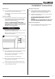
8.2 Locate the control valve on the appliance. It has a single
manual control, see Diagram 35:
Rotate
anti-clockwise
35
Lighting the Pilot
8.3 Push the valve knob in and rotate anti-clockwise slowly until
a click is heard.
The pilot should now be lit.
8.4 Hold in for a further 10 seconds.
When released the pilot should remain lit.
If the pilot does not remain lit, repeat until the operation is
successful.
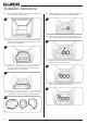
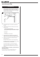
Adjusting the Flame height
8.5 From the pilot position push the valve knob in slightly and
rotate anti-clockwise until the first stop point is felt.
This denotes the lowest setting.
8.6 Push the valve knob in slightly and rotate further in an anti-
clockwise direction.
The final stop point is the highest setting.
Pilot
position
Low Setting
High Setting
Off position
36
Installation Instructions