customerservice@gazebopenguin.com W1207-32 8 X 12 SOLARIUM ASSEMBLY INSTRUCTIONS DO NOT DESTROY THE BOXES UNTIL COMPLETELY ASSEMBLED Assembly by more than one person is suggested. Requires 96” clearance at the wall Base Dimensions 144’’x 94 1/2’’, Largest Dimensions 144’’x98 1/2’’ (see pg.13) ZZZ-187.W1207-32.1129-17.GP.EN.
TOOLS REQUIRED: Screwdriver (Philips #2) (supplied) Knife File (smooth) Needle-nosed pliers Rubber mallet Step ladder (minmum 6' in height) Spatula Power drill Tube of silicon Drill bit 5/16" cement (according to surface) BEFORE STARTING: Ensure that you have a solid base, such as concrete or wooden deck, not slanted more than 1” per 8’. Avoid installing unit adjacent to trees or a sloped roof, as snow and ice may slide onto the solarium and cause it to collapse.
STEP #3 ASSEMBLE PIECES BEFORE SCREWING THEM TO THE WALL Assemble ML-3, N-3, O-3, and MR-3 as shown and position evenly above vertical guides, at 96’’ from the ground. Secure wall track and vertical tracks to brick or cement wall by drilling through the aluminum and using screws Xx-3. Insert the 2 horizontal guides, I3 & J3 at the top of the frame. Make sure the 2 frames are at the correct level, if not, use shims to compensate. Do not use tools to force.
STEP #5 Set right rafter T-3 over last bracket then secure it with Bb-3 screw and continue screwing through joint K-3 with the Bb-3 screw. Secure to Q-3 bracket with self-tapping screw (PQ-3). Repeat on left side with rafter S-3. STEP #6 Set U-3 rafters over the middle of each panel with Bb-3 screws at the top and two (2) Z-3 screws over the brackets on frame manually. Set U-3 rafter on each joint and use Z-3 screws manually. Do not use power drill. ZZZ-187.W1207-32.1129-17.GP.EN.
STEP #7 Remove protective film from two (2) sides of each panel and make sure the top side of the panel faces the sunlight. Insert and slide on the top groove of the rafters all the way to the end. Pp-3 should go first and last with the Qq-3 panels in between. STEP #8 Insert the aluminum middle roof joint between the rafters, making sure the slotted holes are at the bottom. Slide into upper and lower grooves of the rafters then slide all the way into the panels.
STEP #9 Insert the second row of panels into the lower groove on the rafter. Slide panels until they reach the aluminum pieces between the panels and gently tap on the panel to guide it into the aluminum groove. Use a spatula if needed to make it fit. Insert two (2) Pp-3 on either end, then insert the Qq-3 panels. STEP #10 Starting at either end, add X-3 edging and one (1) R-3 bracket and screw with Bb-3 manually, do not use power drill.
STEP #11 On the inside of the solarium under each rafter there are two rows of inserts with threads. Start the upper row with a Jj-3 at either end and screw it with Ff3 and in between the Kk-3 panels. Use Ff-3 screws at the lower row Ll-3 at the 2 ends then the others in between the Mm-3 panels. Make sure screws are manually tight. STEP #12 DOOR UNIT(S) MUST BE ASSEMBLED INSIDE OF SOLARIUM. Slide upper door track F-3 into wheels of sliding door C-3.
STEP #13 Lift up door and track inside of solarium then set it over the door opening by screwing at the top. First use bolts (Ww) and washers (Gg-3) on the inside and female bolts (Cc-3-2) on the outside for the top assembly. See diagram below. Attach lower track with bolts (Cc-3) and washers (Gg-3). Set up door latch on the side required for your door to lock, adjust latch as required. Ww ZZZ-187.W1207-32.1129-17.GP.EN.
STEP #14 Anchor the solarium to the deck or floor securely using screws and shields supplied. See diagram below. SPECIAL NOTES To remove a screen, remove the two (2) screws at the top of the frame then pull sideways to the opposite end of the handles to remove. To remove wind panels, push or pull to one side, making sure that locking pin is not locked then remove panels gently, panels are easy to remove. NOTE: This unit is not waterproof.
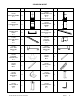
SOLARIUM W1207 DESCRIPTION DESCRIPTION QTY 3 10-497 FRAME NEXT TO DOOR B-3 (Has more holes) 2 10-498 SLIDING DOOR C-3 2 10-499 SLIDING DOOR FRAME D-3 2 11-544 CONNECTING PIECE E-3 8 11-545 TOP DOOR RAIL F-3 2 2 08-138 PLASTIC STOPPER H-3 4 10-500 LEFT SIDE RECEIVER I-3 1 10-501 RIGHT SIDE RECEIVER J-3 1 10-502 CORNER CONNECTOR K-3 2 10-503 TRACK ML-3 1 10-504 TRACK MR-3 1 10-505 TRACK JOINT N-3 1 4 10-507 LEFT GABLE JOINT P-3 1 1 10-509 ROOF RAFTER CAP R-3 7 10-496 REGULAR
DESCRIPTION DESCRIPTION QTY 1 10-511 RIGHT SIDE RAFTER T-3 1 10-512 REGULAR RAFTER U-3 5 10-513 MIDDLE ROOF JOINT V-3 2 10-514 MIDDLE ROOF JOINT W-3 4 10-515 EDGING X-3 2 10-516 EDGING Y-3 4 08-156 SCREW Z-3 10 08-158 BOLT Bb-3 28 08-161 BOLT Cc-3 12 12-037 FEMALE BOLT Cc-3-2 12 08-169 LEFT DOOR LATCH Dd-L-3 2 08-165 RIGHT DOOR LATCH Dd-R-3 2 08-167 SCREW Ee-3 10 08-168 BOLT Ff-3 16 08-187 WASHER Gg-3 22 10 10-517 END ROOF CROSS BAR Jj-3 2 10-510 LEFT SIDE RAFTER S-3 08
DESCRIPTION DESCRIPTION QTY 4 10-519 ROOF TOP REINFORCE Ll-3 2 4 08-134 UPPER DOOR RAIL END CAP Nn 4 8 10-521 ( 51 ½” X 24 ½”) LEFT+RIGHT ROOF PANEL Pp-3 4 8 10-523 LEFT BACK GABLE PANEL Rr-3 1 1 10-525 RIGHT BACK GABLE PANEL Tt-3 1 1 10-527 LEFT WALL GUIDE Vv-3 1 1 10-529 SCREW FOR FIXING TO WALL Xx-3 18 10-530 REGULAR TOP FILLER Yy-3 4 10-531 END TOP FILLER Zz-3 2 12-036 PHILLIPS #2 SCREWDRIVER 1 12-047 BOLT Ww 12 13-045 SELF-TAPPING SCREW PQ-3 4 10-518 REGULAR ROOF CROSS
ZZZ-187.W1207-32.1129-17.GP.EN.
MAINTENANCE NOTES 1. In case of a defective or damaged part, or for any other questions concerning the product, please contact the manufacturer directly. 2. Please have the parts list and part numbers on hand when ordering or requesting replacement parts. 3. The product should not be installed adjacent to trees or a sloped roof. Snow and ice may slide onto the roof and cause it to collapse. 4. While the product is designed for 4 seasons use, the roof must be kept free of accumulation of snow.