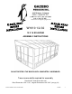
customerservice@gazebopenguin.com W1610 1/2-32 10 X 16 SOLARIUM ASSEMBLY INSTRUCTIONS DO NOT DESTROY THE BOXES UNTIL COMPLETELY ASSEMBLED Two or more adults required for assembly Requires 96” clearance at the wall Base Dimensions 190’’x 118’’, Largest Dimensions 190’’x122’’ (see pg.14) ZZZ-210.W1610-32.1129-17.GP.EN.
TOOLS REQUIRED: Screwdriver Knife File (smooth) Needle-nosed pliers Rubber mallet Step ladder (minmum 6' in height) Spatula Power drill Tube of silicon Drill bit 5/16" cement (according to surface) BEFORE STARTING: Ensure that you have a solid base, such as concrete or wooden deck, not slanted more than 1” per 8’. Avoid installing unit adjacent to trees or a sloped roof, as snow and ice may slide onto the solarium and cause it to collapse.
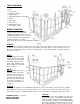
NOTE: Once the wall track is in place, apply silicone along the top of the wall track and at the joint of the two tracks. Silicone is not supplied. STEP #4 Set polycarbonate exposed side on the outside over horizontal left guide I-3, use one (1) Rr-3 panel, one (1) P-3 joint and one (1) Ss-3 panel, then do the right side with one (1) Tt-3 panel, one (1) Q-3 joint and one (1) Uu-3 panel over the J-3 horizontal panel. Secure P-3 and Q-3 to I-3 and J-3 respectively with self-tapping screws (PQ-3). ZZZ-210.
STEP #5 Set right rafter T-3 over last bracket then secure it with Bb-3 screw and continue screwing through joint K-3 with the Bb-3 screw. Secure to Q-3 bracket with self-tapping screw (PQ-3). Repeat on left side with rafter S-3. STEP #6 Set U-3 rafters over the middle of each panel with Bb-3 screws at the top and two (2) Z-3 screws over the brackets on frame manually. Set U-3 rafter on each joint and use Z-3 screws manually. Do not use power drill. Z-3 ZZZ-210.W1610-32.1129-17.GP.EN.
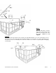
STEP #7 Remove protective film from two (2) sides of each panel and make sure the top side of the panel faces the sunlight. Insert and slide on the top groove of the rafters all the way to the end. Pp-3 should go first and last with the Qq-3 panels in between. STEP #8 Insert the aluminum middle roof joint between the rafters, making sure the slotted holes are at the bottom. Slide into upper and lower grooves of the rafters then slide all the way into the panels.
STEP #9 Insert the second row of panels into the lower groove on the rafter. Slide panels until they reach the aluminum pieces between the panels and gently tap on the panel to guide it into the aluminum groove. Use a spatula if needed to make it fit. Insert two (2) Pp-3 on either end, then insert the Qq-3 panels. STEP #10 Starting at either end, add X-3 edging and one (1) R-3 bracket and screw with Bb-3 manually, do not use power drill.
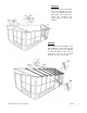
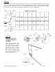
STEP #11 On the inside of the solarium under each rafter there are two rows of inserts with threads, and one crossbeam in two pieces. Start the upper row with a Jj-3 at either end and Kk-3 between panels, screwing them in place with Ff3. Use Ff-3 screws for the lower row Ll-3 at the 2 ends and Mm-3 between panels. Lastly, assemble crossbeam L-1 and L-2, then secure to rafters using bolts Cc-3. Make sure screws are manually tight. Cc-3 STEP #12 DOOR UNIT(S) MUST BE ASSEMBLED INSIDE OF SOLARIUM.
Sliding door should be installed from the inside of the solarium. Sliding door should be installed from the inside of the solarium. STEP #13 Lift up door and track inside of solarium then set it over the door opening by screwing at the top. First use bolts (Ww) and washers (Gg-3) on the inside and female bolts (Cc-3-2) on the outside for the top assembly. See diagram below. Attach lower track with bolts (Cc-3) and washers (Gg-3).
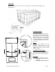
STEP #14 Anchor the solarium to the deck or floor securely using screws and shields supplied. See diagram below. SPECIAL NOTES To remove a screen, remove the two (2) screws at the top of the frame then pull sideways to the opposite end of the handles to remove. To remove wind panels, push or pull to one side, making sure that locking pin is not locked then remove panels gently, panels are easy to remove. NOTE: This unit is not waterproof.
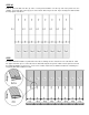
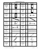
SOLARIUM W1610 1/2 DESCRIPTION DESCRIPTION QTY 4 10-497-12 FRAME NEXT TO DOOR B-3 (with extra holes) 2 2 10-498-12 SLIDING DOOR C-3 2 2 11-544-12 CONNECTING PIECE E-3 14 2 11-546-12 BOTTOM DOOR RAIL G-3 2 4 12-142-12 LEFT SIDE RECEIVER I-3 1 1 10-502-12 CORNER CONNECTOR K-3 2 12-157-12 LEFT CROSSBEAM L-1 1 12-156-12 RIGHT CROSSBEAM L-2 1 10-532-12 TRACK ML-3 1 10-533-12 TRACK MR-3 1 1 10-506-12 RAFTER BRACKET O-3 6 1 12-008-12 RIGHT GABLE JOINT Q-3 1 10-496-12 REGULAR FRAM
DESCRIPTION DESCRIPTION QTY 9 12-146-12 LEFT SIDE RAFTER S-3 1 1 12-148-12 REGULAR RAFTER U-3 7 2 10-514-12 MIDDLE ROOF JOINT W-3 6 10-515-12 EDGING X-3 2 10-516-12 EDGING Y-3 6 08-156-12 SCREW Z-3 14 08-158-12 BOLT Bb-3 32 08-161-12 BOLT Cc-3 25 12-037-12 FEMALE BOLT Cc-3-2 12 08-165-12 RIGHT DOOR LATCH Dd-R-3 2 08-169-12 LEFT DOOR LATCH Dd-L-3 2 08-167-12 SCREW Ee-3 12 08-168-12 BOLT Ff-3 20 08-187 WASHER Gg-3 25 08-193 PLASTIC PLUG Ii-3 12 2 10-518-12 REGULAR ROOF CRO
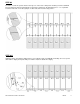
DESCRIPTION QTY DRAWING DESCRIPTION QTY 6 10-519-12 ROOF TOP REINFORCE Ll-3 2 10-520-12 ROOF TOP REINFORCE Mm-3 08-134-12 UPPER DOOR RAIL END CAP Nn 4 08-135-12 SCREW Oo-3 8 4 12-150 (63 ¼ x 23”) REGULAR ROOF PANEL Qq-3 12 1 12-152 LEFT FRONT GABLE PANEL Ss-3 1 1 12-154 RIGHT FRONT GABLE PANEL Uu-3 1 1 10-528-12 RIGHT WALL GUIDE Ww-3 1 10-529-12 SCREW FOR FIXING TO WALL Xx-3 26 10-530-12 REGULAR TOP FILLER Yy-3 6 10-531-12 END TOP FILLER Zz-3 2 12-047-12 BOLT Ww 12 13-045-12
AVAILABLE REPLACEMENT PARTS DESCRIPTION DRAWING DESCRIPTION 10-435-12 PVC WINDOW (in frame) 85-014 REPLACEMENT SCREENING (no frame) 12-176-12 PVC WINDOW for HALF FRAME A-3 1/2 85-417-S ROUND SPLINE FOR SCREENING 10-493 PVC WINDOW (replacement material only) 11-824-12 BOTTOM PLASTIC PANEL (for wall panels) 85-417-P ROUND SPLINE FOR PVC WINDOW 11-825-12 BOTTOM PLASTIC PANEL (for doors) 15-123-12 PIN FOR PVC WINDOW 12-173-12 BOTTOM PLASTIC PANEL FOR HALF FRAME A-3 1/2 13-055 PC WINDOW (for slidin
MAINTENANCE NOTES 1. In case of a defective or damaged part, or for any other questions concerning the product, please contact the manufacturer directly. ZZZ-210.W1610-32.1129-17.GP.EN.
2. Please have the parts list and part numbers on hand when ordering or requesting replacement parts. 3. The product should not be installed adjacent to trees or a sloped roof. Snow and ice may slide onto the roof and cause it to collapse. 4. While the product is designed for 4 seasons use, the roof must be kept free of accumulation of snow. ONE YEAR LIMITED WARRANTY This product has been designed and manufactured to meet the highest standards of quality and durability.