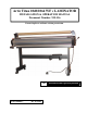
Artic Titan 1040/1064 WF c LAMINATOR INSTALLATION & OPERATION MANUAL Document Number: 930-136 Do not duplicate without written permission. GB Part Number: Rev.
GB The information in this publication is provided for reference and is believed to be accurate and complete. General Binding Corporation (GBC) is not liable for errors in this publication or for incidental or consequential damage in connection with the furnishing or use of the information in this publication, including, but not limited to, any implied warranty of fitness or merchantability for any particular use.
GB TABLE OF CONTENTS Description Page No.
IMPORTANT SAFETY INSTRUCTIONS YOUR SAFETY AS WELL AS THE SAFETY OF OTHERS IS IMPORTANT BEFORE YOU INSTALL OR USE THE MACHINE, READ AND FOLLOW ALL THE SAFETY NOTICES CAREFULLY IN THIS CHAPTER. IN THIS INSTRUCTION MANUAL, AND ON THE LAMINATOR, YOU WILL FIND IMPORTANT SAFETY NOTICES REGARDING THE LAMINATOR. READ ALL OF THE INSTRUCTIONS AND SAVE THESE INSTRUCTIONS FOR FURTHER USE. THE SAFETY ALERT SYMBOL PRECEDES EACH SAFETY NOTICE IN THIS MANUAL.
WARRANTY LIMITED 90- DAY WARRANTY GBC warrants to the original purchaser for a period of ninety days on labor and one year on parts after installation that this laminator is free from defects in workmanship and material under normal use and service. GBC’s obligation under this limited warranty is limited to replacement or repair, at GBC’s option, of any part found defective by GBC without charge for material or labor. THIS LIMITED WARRANTY IS IN LIEU OF ALL OTHER WARRANTIES EXPRESSED OR IMPLIED.
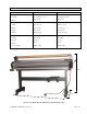
SPECIFICATIONS Artic Titan 1040 WF c Artic Titan 1064 WF c Operating Speed • Variable 0 to 189 fpm(0.8 to 4 m) 0to 18 fpm(0.8 to 4 m) • Fixed 3fpm (0.9 m) 3fpm (0.9 m) • Width 54 in (137 cm) 72.25 in (184 cm) • Height 21 in (53 cm) 48 in (122 cm) • Depth 19 in (48 cm) 26.5 in (67 cm) • Weight 140 lbs. (64 kg) 285 lbs. (129.3 kg) • Voltage 120 V 60 Hz 120 V 60 Hz • Current 0.6 Amps 1.3 Amps • Power 70 W 160 W • U.S.
FCC NOTE FCC Class A Notice - Notification pour les Etats-Unis Note: This equipment has been tested and found to comply with the limits for a Class A digital device, pursuant to part 15 of the FCC rules. These limits are designed to provide reasonable protection against harmful interference when the equipment is operated in a commercial environment.
INSTALLATION This chapter describes how to install the machine. There are no operator serviceable parts to the machine other than periodic cleaning. Refer to the Operator Maintenance chapter. WARNING: Do not attempt to service or repair the laminator. Failure to observe this warning could result severe personal injury or death. Disconnect the plug from the receptacle and contact your dealer or distributor when one or more of the following has occurred.
FEATURES GUIDE This chapter helps you identify the main components of the laminator. Release liner take-up Pressure roller Top film shaft (Not Shown) Idler Control panel Safety sensor Roller pressure handle Feed table Feed table interlock latch (under table) Idler Bottom supply shaft Bottom supply shaft Food switch Fig. 5-1. Laminator Identi cation. (Artic Titan 1064 WF c Shown Without Print Clamp.) TOP FILM SUPPLY SHAFT NIP POINT Holds the film supply on the laminator. (Not shown.
SAFETY SENSORS A. Safety Sensor (Figure 5-2) A The infrared safety sensors prevent entanglement, entrapment, and inadvertent contact with the rollers. The sensors are located on each side of the machine, in front of the bottom roller. They stop the machine when a hand or object blocks the invisible infrared beam if you are not using the foot switch. When the foot switch is used, the speed drops to 3 fpm (0.9 m). WARNING: Keep your fingers and hands away from the nip point.
BOTTOM FILM SUPPLY SHAFT Holds the film or kraft paper on the machine. FILM WEB (Not shown.) The path the laminating film and/or mounting film mounted on the machine takes through the machine. CORE ADAPTORS A. Supply shaft (Figure 5-5) A B B. Take-up shaft (Figure 5-5) C. Core Adaptors (Figure 5-5) D. Gripper (Figure 5-5) C D The core adaptors hold and lock the rolls of film and release liner on the shafts to prevent side to side shifting.
TENSION ADJUSTMENT KNOBS AND MOTOR A. Rewind Motor (Figure 5-7) A B. Film Tension Adjustment Knobs (Figure 5-7) B Fig. 5-7. Artic Titan 1040 WF c Tension Adjustment Knobs and Motor A. Rewind Tension Adjustment Knob (Figure 5-8) A B B. Film Tension Adjustment Knobs (Figure 5-8) The film supply shaft tension knobs allow the operator to increase or decrease the film web tension as needed to reduce curl and wrinkles.
CONTROL PANEL A. Speed Adjustment (Figure 5-10) Turn the speed adjustment knob to set the desired speed. It is adjustable from 0Ft/mn to 18Ft/mn (0.8 to 4 m). B. LED A WARNING: Keep your fingers and hands away from the nip point (the point where the upper and lower rollers meet). Failure to observe this warning could result in severe personal injury. B C. RUN Press and release RUN for continuous running. The green LED illuminates. F C D. STOP Press STOP to stop the machine E.
OPERATION This chapter describes how to use the laminator to: • Operate the machine • Load films (web the machine) • Laminate items • Mount items GENERAL OPERATION These instructions assume that the films have been loaded. For information about loading films, see the Loading Film section in this chapter. A B A. B. C. D. E. SPEED ADJUSTMENT (Figure 6-1) LED RUN STOP REVERSE To run the laminator 1.
LOADING FILM The Artic Titan 1040 WF c and Artic Titan 1064 WF c laminators runs poly-in and poly-out pressure sensitive adhesive (PSA) films. Poly-in means the adhesive side of the film is on the inside of the film roll. Poly-out means the adhesive is on the outside of the film roll. The machine can perform three functions: • Decaling (laminating and applying an adhesive to the back of the item). • Mounting, using one film. • Mounting, using no film.
REMOVING AND INSTALLING THE PRINT CLAMP (Artic Titan 1064 WF c) The print clamp guides prints into the rollers. It should be removed when mounting items to thicker boards. It also needs to be removed to install films and when cleaning the rollers. A. Release Latch (Figure 6-4) B. Print Clamp (Figure 6-4) WARNING: Keep fingers and hands away from the rollers when the machine is running. They could be trapped and crushed in the rollers.
LOADING FILM ONTO THE SUPPLY SHAFTS If you are loading film for the first time, skip these instructions and start with the instructions, To load films onto the supply shafts. If you are replacing existing films, perform the following set of instructions, To remove existing films. To remove existing films: Refer to Figs. 6-6 through 6-8. Fig. 6-6. Roller Pressure Handle Fig. 6-7. Bottom Supply Shaft Bearing out of its Cradle 1. Put the roller pressure handle to Release. 2.
To load films onto the supply shafts: (Figure 6-9) A B C A. Supply shaft B. Take-up shaft C. Core Adaptors D. Gripper 1. If the supply shaft is on the machine, grasp the bearing end and lift it out of the cradle. Then pull the left end out of the brake hub. This applies to the top and bottom supply shafts. 2. Slide the new roll on to the shaft and core adaptors, referring to Fig. 6-3. to determine how the film unwinds from the roll.
LOADING FILM WITH A THREADING CARD Fig. 6-12. Top Film Draped Over the Pressure Rollers and Release Liner Attached to Take-up Fig. 6-13. Bottom Film or Kraft Paper Stuck to Top Film Fig. 6-14. Threading Card Inserted Between Films The following procedure uses a film threading card that is sometimes provided with new rolls of film. If one is not provided, a scrap of cardboard or poster board with a straight edge is suitable. Either can be reused.
LOADING FILM BY TRACKING NEW FILM TO EXISTING FILM Fig. 6-15. New Films Tacked to Old Films The following describes a method for loading film whereby the existing film on the rollers may be used in place of the threading card to draw the new film through the laminator. Leading edges of the new film will be overlapped onto the adhesive of the old film. The existing film and the new film will be pulled through the laminator together. 1. Remove the print clamp (Artic Titan 1064 WF c) and feed tray.
DECALING IN TWO PASSES Decaling is where you laminate items and then mount them on other materials such as Foam Core or mounting board. It is performed in two passes. The first pass laminates and applies the mounting adhesive, encapsulating the item. The second pass mounts it on rigid material. This two pass operation requires pressure sensitive laminating film on the top supply shaft and pressure sensitive mounting film on the bottom supply shaft. Refer to Fig.
MOUNTING TIPS FOR THREADING PRESSURE SENSITIVE ADHESIVE (PSA) FILM • Use kraft paper for one-sided lamination. • Refer to Fig. 6-17 for the proper film configuration. • Whenever possible, pull the remaining web of film out the front of the laminator after the finished item has been removed. PRE-TREATING BOARDS You may wish to pre-coat mounting boards ahead of time with PSA mounting film. To pre-treat boards: Fig. 6-19. Laminator Ready for Pre-treating Boards 1.
FILM TENSION A B C Proper film tension, known as brake tension, is the minimum amount required to eliminate wrinkles in the finished item. As the film roll becomes smaller, tension increases, thus the adjustment needs to be loosened. Film tension should be checked occasionally to assure that the adjustment is correct. The film should be taut with no gaps between the film and pressure rollers. A properly adjusted roll of film should not require excessive force to turn by hand.
TESTING THE WEB After webbing the machine, it is important that the films run straight and evenly. To test the web: 1. Set the roller pressure handle to an appropriate position. 2. Press RUN or the foot switch and run approximately 6 in. (10 cm) of laminate. 3. Press STOP or release the foot switch. 4. Visually inspect the top and bottom films where they enter the nip. The films should be tight against the rollers at both ends.
OPERATOR MAINTENANCE CARING FOR THE Artic Titan 1040 WF c OR 1064 WF c LAMINATOR The only maintenance required by the operator is to periodically clean the rollers. The following procedure will help keep them free of dirt and adhesive, which has been deposited along the edge of the laminating film. Proper alignment of the rolls of film reduces the amount of adhesive on the rollers. Perform only the routine maintenance procedures referred to in these instructions.
TROUBLESHOOTING SYMPTOM POSSIBLE CAUSE CORRECTIVE ACTION Power lamp does not illuminate on the control panel when the ON/OFF switch is in the ON position. Laminator not connected to electrical supply. Insert attachment plug into receptacle. Rollers do not turn. Infrared eyes blocked. Unblock infrared eyes. Feed tray interlock latch not in place. Slide interlock latch all the way to the left into the side frame. Adjust tension per Film Tension section. Laminated items are curling.