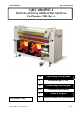
GBC 4064WF-1 Operation Manual GBC 4064WF-1 INSTALLATION & OPERATING MANUAL Part Number: TBD, Rev A. Part Number: TBD © 2009 GBC an ACCO Brands Co.
GBC 4064WF-1 Operation Manual GB The information in this publication is provided for reference and is believed to be accurate and complete. General Binding Corporation (GBC) is not liable for errors in this publication or for incidental or consequential damage in connection with the furnishing or use of the information in this publication, including, but not limited to, any implied warranty of fitness or merchantability for any particular use.
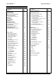
GBC 4064WF-1 Operation Manual TABLE OF CONTENTS Description Cover Legal Disclaimer Table of Contents Important Safety Instructions Important Safeguards General ,Electric & Service Warranty Specifications Pre- Installation Installation Front Control Guide Lamination Processes Selecting Gaps and Pressures AccuShield Mode Saving Temps and Speeds LCD Quick Reference LCD Detailed Reference Sheet Features Guide Emergency-Stop Buttons Heated Main Roll-Top Heated Main Roll-Bottom Media Pressure Plate Front Table
GBC 4064WF-1 Operation Manual IMPORTANT SAFETY INSTRUCTIONS YOUR SAFETY AS WELL AS THE SAFETY OF OTHERS IS IMPORTANT TO GBC. IN THIS INSTRUCTION MANUAL AND ON THE PRODUCT, YOU WILL FIND IMPORTANT SAFETY MESSAGES REGARDING THE PRODUCT. READ THESE MESSAGES CAREFULLY. READ ALL OF THE INSTRUCTIONS AND SAVE THESE INSTRUCTIONS FOR LATER USE. THE SAFETY ALERT SYMBOL PRECEDES EACH SAFETY MESSAGE IN THIS INSTRUCTION MANUAL. THE SYMBOL INDICATES A POTENTIAL PERSONAL SAFETY HAZARD TO YOU OR OTHERS.
GBC 4064WF-1 Operation Manual WARRANTY Limited 90- Day Warranty GBC warrants to the original purchaser for a period of ninety days on labor and one year on parts after installation that this laminator is free from defects in workmanship and material under normal use and service. GBC’s obligation under this limited warranty is limited to replacement or repair, at GBC’s option, of any part found defective by GBC without charge for material or labor.
GBC 4064WF-1 Operation Manual PRE-INSTALLATION Before a 4064WF-1 Laminator can be installed, ensure the following requirements are met: 1. 2. 3. Are doorways and hallways wide enough for the laminator to be moved to the installation site? Is there ample room for the laminator? • A work area must be established that allows for operation in both the front and rear of the laminator and provides space for efficient material flow.
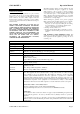
GBC 4064WF-1 Operation Manual FRONT CONTROL GUIDE FIGURE 1. 1. LCD: • The LCD will display the settings the machine is currently set for. • Illuminates when the laminator is plugged in and POWER ON/OFF is in the on, (I), position. Displays settings for the top heater, bottom heater, speed, job mode, and ready/wait. • TOP: -refers to the Top Main Rollers temperatures setting. • BOT: - refers to the Bottom Main Rollers temperatures setting. • Mode: -Displays the current Machines Mode.
GBC 4064WF-1 Operation Manual There are 2 Lamination Processes on 4064WF-1, LAM and ACCUSHIELD. LAM: This setting is intended to be used when an operator wants to use both the top and bottom heater, and wants full downward pressure on the Main Rolls. To Select a Different Pressure or Gap: Press STOP to stop the machine. Press JOB. Rotate the MASTER DIAL. The Pressure and Gap selections are: LAM, 0”, 1/16”, 1/8”, 3/16”, ¼”, 3/8”, ½”, ¾”, 1” FIGURE 1. .
GBC 4064WF-1 Operation Manual A-SHLD: This setting is intended to be used when an operator wants to run ACCUSHIELD. This process requires the rollers to rotate as soon as the solenoids are activated. ACCUSHIELD also requires that the lower roll NOT heat up. All the settings in A-SHLD will have: The lower roll pre-set to 32*F Rollers will rotate as soon as the rollers drop. Rollers will rise before the rollers stop rotating. To Select ACCUSHIELD Mode: Press STOP. Press JOB.
GBC 4064WF-1 Operation Manual Saving Temps and Speeds The operator is able to save Temps and Speeds for certain processes on the 4064WF-1. When operating the laminator in the lamination mode, the operator can save the Speed, Top Heat, & Bottom Heat. For each Gap or Pressure setting, one job can be saved. Ex: When the GAP is set on 0”, the TOP & BOTTOM Heat can be saved, as well as the speed. To Save the TOP Heat: Press “TOP TEMP” Rotate the Master Dial until the desired Temp is displayed.
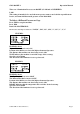
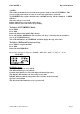
GBC 4064WF-1 Operation Manual LCD QUICK REFERENCE SHEET Figure 1 TOP: 265*F WAIT BOT: 032*F SPD: 03ft POS: LAM FRONT FRONT TENSION ERR!!!! FIGURE 1: When jobs are changed, the shim dials will automatically rotate to the desired setting. Front Tension Error indicates that the Front Shim Dial has not located the desired setting. • Make sure Air is applied to the machine. • Re-set the Main Power.
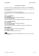
GBC 4064WF-1 Operation Manual LCD DETAILED REFERENCE SHEET FIGURE 1 TOP: 230*F BOT: 230*F POS: ½” DISTANCE: 00000ft. FIGURE 3 WAIT SPEED: 05ft REAR TOP: 230*F BOT: 230*F POS: ½” WAIT SPEED: 05ft REAR SEARCHING FIGURE 3: FIGURE 1: • Top Temp is set for 230*F • Top Temp is set for 230*F • Bottom Temp is set for 230*F • Bottom Temp is set for 230*F • Position of Rollers or Job is ½ inch. • Position of Rollers or Job is ½ inch. • Distance the machine ran is 00000ft.
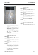
GBC 4064WF-1 Operation Manual FEATURES/ACCESORIES GUIDE Refer to the following pages for detailed information on the Features FIGURE A 2 Table Idler: (FIGURE C, Item 2) The Table Idler assists feeding of images into the web. It is helpful in roll to roll operation and helps move large rigid panels through the nip. FIGURE D 1. Emergency Stop Buttons: (FIGURE A, Item 1) Four E-Stop buttons are on the Laminator located on the top of the Laminator at all four corners.
GBC 4064WF-1 Operation Manual To increase PSI, rotate the knob cock-wise. To reduce the amount of PSI, turn the knob counter clock-wise. FIGURE G 2. Lower Pull Roll: (FIGURE I, Item 2) The Pull rollers located at the back of the laminator are motor driven. They simultaneously pull the film and image. The Lower Pull Roller is clutched. 3. Rear Table: (FIGURE I, Item 3) Used to support finished Media and used when running the machine from the rear. 4.
GBC 4064WF-1 Operation Manual FIGURE L FIGURE N A 1. Pull Roll Clutch: (FIGURE L Item 1) The Pull Roll Clutch provides tension on the laminated film between the main rolls and pull rolls as the material is cooling. B FIGURE M 1. Main Power Cord. (FIGURE N Item A) The Main Power Cord Plugs into the Main Power Supply. See Power Requirements in the Specs part of the manual for required Voltage and Amperage. 2. Foot Switch.
GBC 4064WF-1 Operation Manual SEQUENCE OF OPERATIONS Diagram #1 GBC U.S 4064WF-1 Effect of Fiber Optics on sequence of operation Modes Situation 1 Situation 2 Situation 3 Machine Run Mode Normal operation (No Interruption to any safety circuitry & Fiber optic beam) Interrupted fiber optic beam or opened any safety circuitry. Fiber optic beam cleared + all safety circuitries are closed Control panel: Forward Speed: Zero to Max.
GBC 4064WF-1 Operation Manual OPERATING INSTRUCTIONS Film Loading & Threading The top and bottom rolls of laminating film must be of the same width and be present simultaneously. A Small amount of adhesive will “squeeze out” during Lamination. Hardened adhesive deposits can damage the heat rollers. CAUTION: Adhesive will deposit on the rollers if: • Only one roll is used. n ly-i Po • Different widths of rolls are loaded together.
GBC 4064WF-1 Operation Manual Webbing Thermal Film Using Threading Card THERMAL LAMINATE CAUTION: The laminator rollers will be hot and can burn you. For pressure sensitive film (PSA), refer to the section titled WEBBING: USING FILM THREADING CARD FOR PSA FILM. 1. Turn the Main Power ON /OFF to On. 2. Set top and bottom temperature with regards to the film type used. 3. Ensure no brake tension is applied to the film shafts. 4.
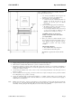
GBC 4064WF-1 Operation Manual Webbing PSA Film/Mount Threading Card Adhesive Using The laminator should be cool to the touch before Proceeding. FIGURE 22 REWIND TUBE PSA Film Mount Adhesive FIGURE 23 PSA Film CHILLED ROLLER 1. Turn the Power ON /OFF to On 2. Load the rolls of film as illustrated in (Fig. 22). Ensure no brake tension is applied to the film shafts. 3. Pull the top roll of film down under the idler bar and up to the upper front rewind tube. 4.
GBC 4064WF-1 Operation Manual Start Laminating 1. At this point you should have your laminator webbed with the appropriate material for your application. 2. The feed table should be in the normal operating position. 3. Close the main and Pull roll nips. Rollers should be closed. 4. Speed is set to 3 or less and front () motor direction is selected. 5. Press the start ( ) button. 6. Set main roller pressure between 40% – 60% for laminating by turning the main roll lift handle.
GBC 4064WF-1 Operation Manual Method for Tacking New Film to Existing Film (1) The following describes a method for loading film whereby the existing film present on the heat rollers may be used in place of the threading card to draw the new film through the laminator. The adhesive of the existing film must be tacky or liquefied. Leading edges of the new film will be overlapped onto the tacky adhesive of the old film. The existing film and the new film will be pulled through the laminator together.
GBC 4064WF-1 Operation Manual To unweb the laminator Unweb the laminator if you are changing film widths, cleaning the rollers or have finished using the machine for the day. (2) (1) CAUTION: Do not cut yourself (3) 1. Using a slitter, cut (1) the output from the web (Fig. 29). 2. Cut (2) remaining top film web between the idler bar and heat roller. PSA film cut the release liner too. 3. Cut (3) the film web between the lower film supply and the idler bar (Fig. 29). (2) .......
GBC 4064WF-1 Operation Manual APPLICATIONS Tips for Pre Coating Boards MOUNT ADHESIVE LEADER BOARD TRAILOR BOARD BOARDS FIGURE 31 1. Load the laminator as illustrated in (Fig. 31). Remove chill idler. 2. The width of the roll should not exceed the width of the board by more than 1/2 in. (1.3 cm). 3. Use a leader board to set the main roller and pull roller pressure prior to webbing. 4. Use a leader board to start the run and a trailer board to finish the run. 5.
GBC 4064WF-1 Operation Manual Tips for Creating a Decal 1. Load the laminator as illustrated in Fig. 34. 2. The over laminate may be PSA or thermal type. 3. If using thermal type, pay attention to the Polyin/Poly-out rule. 4. Run a test material prior to running the actual image to ensure flat output. 5. Use minimal brake tension to achieve quality output. 6. Do not web the PSA mount adhesive around the lower web idler.
GBC 4064WF-1 Operation Manual Tips for AccuShield THERMAL FILM IMAGE OPTIONAL SEPERATOR BAR OUTPUT ROLL TO ROLL OPTION KRAFT PAPER OPTION 1. Load the laminator as illustrated in Fig. 37. 2. You must have the Separator bar option to accurately run this material. See your Sales Rep for ordering the Separator Bar. 3. Set Top Temp to 280* F(135* C) and a speed setting no greater than 4. 4. Liner rewind tension will be greater than normal operating standard 5.
GBC 4064WF-1 © 2009 GBC an ACCO Brands Co.
GBC 4064WF-1 © 2009 GBC an ACCO Brands Co.
GBC 4064WF-1 © 2009 GBC an ACCO Brands Co.
GBC 4064WF-1 © 2009 GBC an ACCO Brands Co.
GBC 4064WF-1 © 2009 GBC an ACCO Brands Co.
GBC 4064WF-1 Operation Manual SPEED / TEMPERATURE CONTROL This is only a general reference guide. Different settings may be suitable as the warm up time, lamination time and materials change. Factors that may affect the speed and temperature parameters; 1. Image length thickness 2. Image width and ink coverage 3. Ink coverage 4. Paper type 5. Laminate thickness 6. Operating environment 7. Condition of the rollers 8. Line voltage (effects heaters) 9. Using cooling features.
GBC 4064WF-1 Operation Manual FILM TENSION Proper film tension, known as brake tension, is the minimum amount required to eliminate wrinkles in the finished item. The film should be taut. A properly adjusted roll of film should not require excessive force to turn by hand. Film tension should be enough to introduce a minor amount of drag as the film unrolls. Insufficient tension causes wrinkles, while too much tension causes stretching (necking).
GBC 4064WF-1 Operation Manual MAINTENANCE Caring For The GBC 4064WF-1 Laminator GBC offers Cleaning kits as well as Extended Maintenance Agreements. Contact your local GBC Service Representative or your dealer/distributor for additional information. The only maintenance required by the operator is to periodically clean the heat rollers and schedule semi annual maintenance checks.
GBC 4064WF-1 Operation Manual TROUBLE SHOOTING GUIDE SYMPTOM POSSIBLE CAUSE The control panel display does not illuminate when POWER ON/OFF is in the ON, marked “I”, position Heat rollers do not turn when I CORRECTIVE ACTION Laminator not connected to electrical supply Insert attachment plug into receptacle Blown out fuse. Feed table not properly installed. Check fuses. Tilt feed table and properly replace it. Pull out on the E-STOP push button. Disengage the footswitch mode. Clear nip area.