640t Laminator INSTALLATION & OPERATION MANUAL Document Number: 04048E001 Do not duplicate without written permission.
640t – Installation and Operating Instructions The information in this publication is provided for the use of GBC customers. General Binding Corporation (GBC), and it’s parent ACCO Brands Corporation, make no guarantees or warranties in connection with this publication.
640t – Installation and Operating Instructions Table of Contents 1. Safety Warnings..................................................................1-1 General.....................................................................1-1 Electrical...................................................................1-2 2. Warranty Limited 90-Day Warranty.........................................2-1 For European Union Residents Only........................2-1 3. Specifications Specifications......................
640t – Installation and Operating Instructions Page ii
640t – Installation and Operating Instructions 1. Safety Your safety, as well as the safety of others is important. Before you install or use the machine, read and follow all the safety notices carefully in this chapter. In this instruction manual, and on the laminator, you will find important safety notices regarding the laminator. Read all of the instructions and save these instructions for further use. The safety alert symbol precedes each safety notice in this manual.
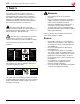
40t – Installation and Operating Instructions Electrical The laminator should be connected only to a source of power as indicated in these instructions and on the serial plate located on the rear of the laminator. Contact an electrician should the attachment plug provided with the laminator not match the receptacles at your location. WARNING: Do not attempt to service or repair the laminator. Failure to observe this warning could result in severe personal injury or death.
640t – Installation and Operating Instructions 2. Warranty Limited 90-Day Warranty GBC warrants to the original purchaser for a period of ninety days on labor and on parts after installation that this laminator is free from defects in workmanship and material under normal use and service. GBC’s obligation under this limited warranty is limited to replacement or repair, at GBC’s option, of any part found defective by GBC without charge for material or labor.
640t – Installation and Operating Instructions Page 2-2
640t – Installation and Operating Instructions 3. Specifications 640t Maximum film roll diameter Operating Speed • Variable • Fixed Dimensions • Width • Height • Depth • Weight Electrical Requirements • Voltage • Current • Power • U.S. Receptacle 5 inches 3 to 16 fpm (0.8 to 4 m) 3 fpm (0.9 m)* 78 in (198 cm) 48 in (122 cm) 30 in (76 cm) 350 lbs. (273 kg) 220 VAC 60 Hz 9 Amps 2000 W NEMA 6-15R *NOTE: The 640t laminator has a fixed speed in reverse or when using the foot pedal with the feed table removed.
640t – Installation and Operating Instructions FCC Note Modifications This equipment has been tested and found to comply with the limits for a Class A digital device, pursuant to part 15 of the FCC Rules. These limits are designed to provide reasonable protection against harmful interference when the equipment is operated in a commercial environment.
640t – Installation and Operating Instructions 4. Installation This chapter describes how to install the machine. There are no operator serviceable parts to the machine other than periodic cleaning. Refer to “7. Operator Maintenance” on page 7-1. Installation To set up the laminator for the first time: 1. WARNING: Do not attempt to service or repair the laminator. Failure to observe this warning could result in severe personal injury or death.
640t – Installation and Operating Instructions Page 4-2
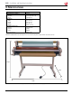
640t – Installation and Operating Instructions 5. Feature guide This chapter helps you identify the main components of the laminator. Release liner take-up Pressure roller Top film supply shaft Safety sensor Control panel Feed table Feed table interlock latch (under table) Roller pressure handle Bottom supply shaft Foot switch Fig. 5-1. Laminator Identification. Film Shafts A. Release Liner Take-up Rewinds the release liner of pressure sensitive films.
640t – Installation and Operating Instructions Idler Bars, Unwind Shafts, Rewind Shafts Rollers and Safety Sensor Fig. 5-4 Upper and Lower Main Rollers and Safety Sensor. Fig. 5-3. Idler Bars, Unwind Shafts, Rewind Shafts. A. Upper Rewind B. Upper Unwind/Supply Shaft C. Lower Unwind/Supply Shaft The Lower Idler directs Kraft Paper or images to the Lower Main Roller. D. Upper Idler The Upper Idler directs the film around the roller and is used as a point of release when using PSA films.
640t – Installation and Operating Instructions Emergency Stop and Table Control Panel and Print Clamp Fig. 5-5. Emergency Stop Button and Table Components. A. Table Interlock Hole When the table is down, the latch engages this hole. B. Table Interlock The Table Interlock latch locks the feed table into position and activates an interlock switch. The latch is located on the left, underside of the feed table. Move the latch to the right to release the table.
640t – Installation and Operating Instructions Tension Controls Fig. 5-7. Tension Knobs and Brakes Roller Pressure Handle Fig. 5-8. Roller Pressure Handle. A. Release Liner Tension Knob A. Mounting & Laminating Presets Use the Release Liner Tension Knob to increase and decrease the amount of Pull that is being applied to the release liner. This prevents the release liner from being pulled into the laminator or the film from wrapping around the rewind tube.
640t – Installation and Operating Instructions Media Core Adapter Rewinder Fig. 5-10. Rewinder Components. A. Rewinder Core Adapters Fig. 5-9. Media Core Adapter. The Media Core Adapters hold and lock the rolls of film and release liner on the shafts to prevent side to side shifting. Grippers on the Core Adapters ensure proper tension on the film. The Supply Shaft Core Adaptors lock in place with a set screw. The release liner take-up Core Adaptors are held in place by friction.
640t – Installation and Operating Instructions Power Power Cord and Foot Switch Fig. 5-11. Power Panel. A. On/Off Power Switch The On/Off Power Switch is located at the back of the machine. Press the “I” on the switch to turn it on. The LCD will illuminate. The off position, marked “0”, turns the machine off. B. Circuit Breaker The Circuit Breaker will trip if there is too much load. Wait for 1 minute after the Circuit Breaker trips and press the switch to reset.
640t – Installation and Operating Instructions Control Panel Temp Section D. MES (Measure) A C Press MES to show the actual Top Main Roller Temperature. E. Temp Arrow Up B To increase the Top Main Roller temperature, press and hold. F. Temp Arrow Down To decrease the Top Main Roller temperature, press and hold. G. HOT D E G F H I K J L M For the factory preset temperature of the Top Main Roller, press HOT. H.
640t – Installation and Operating Instructions Page 5-8
640t – Installation and Operating Instructions 6. Operation This chapter describes how to use the laminator to: • • • • Operate the machine Load films (web the machine) Laminate items Mount items To run the laminator: • • • General Operation These instructions assume that the films have been loaded. For information about loading films, see “Loading Film” on page 6-2. Turn the laminator On (I) with the power switch located at the back of the machine. The Display (“Fig. 6-1. Control Panel.”) is: 1.
640t – Installation and Operating Instructions Loading Film IMPORTANT: The top and bottom rolls of laminating film must be the same width. The 640t laminator runs poly-in and poly-out pressure sensitive adhesive (PSA) films. Poly-in means the adhesive side of the film is on the inside of the film roll. Poly-out means the adhesive is on the outside of the film roll. Always change the top and bottom supply rolls at the same time.
640t – Installation and Operating Instructions Removing and Installing the Print Clamp Removing and Installing the Feed Table The print clamp guides prints into the rollers. It should be removed when mounting items to thicker boards. It also needs to be removed to install films and when cleaning the rollers. The feed table should not be removed except to install films. When the table is off, the laminator runs at a fixed speed of 3 fpm (0.9 m).
640t – Installation and Operating Instructions Loading Film Onto the Supply Shafts If you are loading film for the first time, skip these instructions and start with the instructions, “To load films onto the supply shafts:” on page 6-5. If you are replacing existing films, perform the following set of instructions, “To remove existing films:” on page 6-4. 3. If the unwind/supply shaft (“Fig. 6-7. Unwind/ Supply Shafts.”) is on the machine, grasp the bearing end and lift it out of the cradle (“Fig. 6-8.
640t – Installation and Operating Instructions To load films onto the supply shafts: 1. If the supply shaft is on the machine, grasp the bearing end and lift it out of the cradle. Then pull the left end out of the brake hub. This applies to the top and bottom supply shafts. 2. Slide the new roll on to the shaft and core adaptors, referring to “Fig. 6-3. Poly-in and Poly-out Films.” on page 6-2 to determine how the film unwinds from the roll.
640t – Installation and Operating Instructions Fig. 6-9. Top Film Draped Over the Pressure Rollers and Release Liner Attached to Take-up. 6. Pull the mounting film (or Kraft paper) up to about even with the top of the top pressure roller without touching the sticky laminating film. 7. While pulling evenly, carefully align the edges of the mounting film with the laminating film, and press the two together. It is important that the tension is even from one end of the supply rolls to the other. Fig. 6-11.
640t – Installation and Operating Instructions Loading Film by Tacking New Film to Existing Film The following describes a method for loading film whereby the existing film on the rollers may be used in place of the threading card to draw the new film through the laminator. Leading edges of the new film will be overlapped onto the adhesive of the old film. The existing film and the new film will be pulled through the laminator together. 1. Remove the print clamp and feed tray.
640t – Installation and Operating Instructions Decaling in Two Passes 4. Guide the item into the rollers. Decaling is where you laminate items and then mount them on other materials such as Foam Core or mounting board. It is performed in two passes. The first pass laminates and applies the mounting adhesive, encapsulating the item. The second pass mounts it on rigid material. 5. Once the item has cleared the back of the machine, release the foot switch or press STOP. 6.
640t – Installation and Operating Instructions 10. After the board has cleared the rollers, release the foot switch or press STOP. 6. Press STOP when the last board exits the machine. Mounting Mounting Only Tips For Threading Pressure Sensitive Adhesive (PSA) Film This process requires a decaled item with PSA mounting adhesive. Refer to the To run the second pass instructions in the Decaling In Two Passes section of this chapter.
640t – Installation and Operating Instructions Film Alignment and Tension Film Tension Film Alignment Proper film tension, known as brake tension, is the minimum amount required to eliminate wrinkles in the finished item. As the film roll becomes smaller, tension increases, thus the adjustment needs to be loosened. Film tension should be checked occasionally to ensure that the adjustment is correct. The top and bottom supply rolls must be aligned as closely as possible.
640t – Installation and Operating Instructions Testing the Web After webbing the machine, it is important that the films run straight and evenly. To test the web: 1. Set the roller pressure handle to an appropriate position. 2. Press RUN or the foot switch and run approximately 6 in. (10 cm) of laminate. Clearing a Film Jam (Wrap-up) Film jams (wrap-ups) may occur if the film is loaded backwards or if the area at which film exits the equipment is blocked. The film, when jammed, wraps around the rollers.
640t – Installation and Operating Instructions Lamination Guide This manual provides general guidelines and is only a general reference guide. Different settings may be suitable as the lamination time and materials change. Test materials before running good materials through the machine. • Do not attempt to laminate abrasive or metal objects such as staples, paper clips and glitter, as they may damage the rollers. • Do not force items into the nip area of the rollers.
640t – Installation and Operating Instructions 7. Operator Maintenance Caring for the 640t Laminator The only maintenance required by the operator is to periodically clean the rollers. The following procedure will help keep the rollers free of dirt and adhesive, which has been deposited along the edge of the laminating film. Proper alignment of the rolls of film reduces the amount of adhesive on the rollers. Perform only the routine maintenance procedures referred to in these instructions.
640t – Installation and Operating Instructions Troubleshooting Symptom Possible Cause Corrective Action LCD does not illuminate on Laminator not connected to electrical the control panel when the supply. ON/OFF switch is in the ON position. Circuit Breaker tripped. Insert attachment plug into receptacle. Rollers do not turn. Infrared eyes blocked. Unblock infrared eyes. Feed tray interlock latch not in place. Slide interlock latch all the way to the left into the side frame.
640t – Installation and Operating Instructions Notes Page 7-3
ACCO Brands 300 Tower Parkway Lincolnshire, IL 60069-3640 In USA call 800.541.0094 ACCO Canada - Brampton 5 Precidio Court Brampton, ON L6S-6B7 CANADA Au Canada, composez le 800.463.2545 www.accobrands.com www.gbc.com www.acco.ca ACCO MEXICANA S.A. DE C.V. Circuito de al Industria Norte No. 6 Parque Industrial Lerma, Lerma Edo. de México C.P. 52000 México En México llame al 52.55.15005700 Desde el extranjero: 52.72.22656501 www. accomexico.com www.gbc.com.mx © 2009 ACCO Brands. All rights reserved.