Item #TBD ® Model #FC120-CARL UL Model #TBD USE AND CARE GUIDE 48 IN LED INDOOR AIR FILTERING CEILING FAN Questions, problems, missing parts? Before returning to the store, call Hampton Bay Customer Service 8 a.m. - 7 p.m., EST, Monday-Friday, 9 a.m. - 6 p.m., EST, Saturday 1-855-HD-HAMPTON HAMPTONBAY.COM To view an instructional video on how to install this product: 1. Go to ww.homedepot.
Table of Contents Table of Contents ................................................................ 2 Assembly.............................................................................. 7 Safety Information ............................................................... 2 Operation ........................................................................... 15 Warranty ............................................................................... 3 Care and Cleaning ................................
Warranty The supplier warrants the fan motor to be free from defects in workmanship and material present at time of shipment from the factory for a lifetime after the date of purchase by the original purchaser. The supplier also warrants that all other fan parts, excluding any glass or acrylic blades, to be free from defects in workmanship and material at the time of shipment from the factory for a period of one year after the date of purchase by the original purchaser.
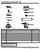
Pre-Installation (continued) HARDWARE INCLUDED NOTE: Hardware not shown to actual size. BB AA Part Description Quantity AA Wiring cap 6 BB Screw 1 4 HAMPTONBAY.COM Please contact 1-855-HD-HAMPTON for further assistance.
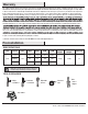
Pre-Installation (continued) PACKAGE CONTENTS A G B H C I D J E K F Part Description Quantity A Mounting bracket 1 B Hanger rod assembly 1 C Canopy 1 D Canopy cover 1 E Lower canopy assembly 1 F Fan-motor assembly 1 G Purification assembly 1 H Lampshade 1 I Filter screen 1 J Blade 5 K Controller assembly includes 1 receiver, 1 remote control, 2 batteries and 2 wires 1 IMPORTANT: This product and/or components are governed by one or more of the following U.S.
Installation MOUNTING OPTIONS WARNING: or personal injury, mount to an outlet box marked “Acceptable for fan support of 35 lbs. (15.9 kg) or less,” and use the screws provided with the outlet box. An outlet box commonly used for the support of lighting NOTE: You may need a longer downrod to maintain proper blade clearance when installing on a steep, sloped ceiling. The maximum angle allowable is 20° away from horizontal. electrician.
Assembly - Standard Ceiling Mount 1 Preparation for assembly □ Remove the 15 preassembled screws (BB), 3 preassembled outer tooth washers (RR) and preassembled screws (QQ) from the motor housing (F) and place them in a safe secure place. Do not discard. BB F RR QQ 7 HAMPTONBAY.COM Please contact 1-855-HD-HAMPTON for further assistance.
Assembly - Standard Ceiling Mount 2 Install the hanger rod assembly □ Loosen the two screws (CC) on the motor assembly (F). Disassemble the parts on the hanger rod assembly (B) R pin (FF), cross pin (JJ), screw (DD), external washer (EE), hanger ball (HH), and cross pin (GG). CC DD EE GG HH II JJ FF F Hanger rod assembly (B) □ Pass the wires on the motor assembly (F) through the lower canopy assembly (E), upper canopy (C), hanger ball (HH), and down rod (II).
Assembly - Standard Ceiling Mount □ Pass the cross pin (GG) into the down rod (II), and adjust the position of the hanger ball (HH). II HH □ GG Tighten the hanger ball (HH) on the hanger rod (B) with the screw (DD) and the external washer (EE). B 9 HH EE DD HAMPTONBAY.COM Please contact 1-855-HD-HAMPTON for further assistance.
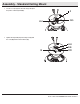
Assembly - Standard Ceiling Mount 3 Install the hanger bracket assembly WARNING: To reduce the risk of fire, electric shock, or other personal injury, mount the fan to an outlet box or supporting system marked acceptable for fan support and use the mounting screws that come with the outlet box (not included). □ Put the mounting bracket (A) into the screw (LL) (not included) on the outlet box (KK) in the direction as shown in the figure, and then tighten the screw (LL).
Assembly - Standard Ceiling Mount 4 Hang the motor assembly NOTE:It is required to clamp the base of the hanger bracket assembly (A) into the groove of the hanger rod assembly (B). WARNING: The tab (XX) is only to balance the fan while may result in the tab (XX) breaking, causing the fan to fall. The tab must pass from the inside to the outside of the canopy. WARNING:When hanging the fan on the tab (XX) it is critical that you use one of the non-slotted (round) holes in the canopy (C).
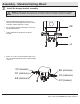
Assembly - Standard Ceiling Mount 5 Install the hanger bracket assembly □ Insert the receiver (MM) into the hanger bracket assembly (A). MM A □ Insert the wire harness (NN) and wire harness (OO) into the receiver (MM). MM NN OO 12 HAMPTONBAY.COM Please contact 1-855-HD-HAMPTON for further assistance.
Assembly - Standard Ceiling Mount 6 Wiring the receiver Ground conductor Yellow Green Red Hot Black Neutral White □ Connect the receiver as shown in the wiring diagram. □ Follow the steps below to connect the fan to your house supply wires. □ Connections between the motor assembly and the receiver: Butt slice the white terminal on the fan to the white terminal on the receiver with the Orange/Grey/White. Butt slice the black terminal on the fan to the black terminal on the receiver.
Assembly - Standard Ceiling Mount 7 Install the canopy and the canopy cover □ Arrange the connected wiring harness and cover it with the canopy (C). □ Rotate the canopy (C) clockwise onto the screw heads (CC). Reinstall the previously-removed screws (CC) and washers (EE) in Step 2. Tighten all the screws (CC) to secure the canopy (C). CC EE EE CC C CC □ Rotate the canopy cover (D) counterclockwise to attach it. D 14 HAMPTONBAY.COM Please contact 1-855-HD-HAMPTON for further assistance.
Assembly - Standard Ceiling Mount 8 □ Install the fan blades Insert the fan blade (J) into the installation groove of the middle ring (PP), and attach the fan blade (J) with the previously-removed screws (BB) in Step 1. PP J BB 15 HAMPTONBAY.COM Please contact 1-855-HD-HAMPTON for further assistance.
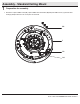
Assembly - Standard Ceiling Mount 9 □ Install the purification assembly Hold and press, the two bosses on the filter holder (SS) at the same time and pull out the filter holder. NOTE: Insert the filter (TT) before hanging the purification assembly (G). □ Insert the filter (TT) into the filter holder (SS), and then insert the filter holder (SS) into the purification assembly (G). TT G SS 16 HAMPTONBAY.COM Please contact 1-855-HD-HAMPTON for further assistance.
Assembly - Standard Ceiling Mount □ Connect the wire harness with the wiring cap (AA). □ Use electrical tape to stick the connected wires on the receiver cover. NOTE: Connect the black wire harness to the black wire and the white wire harness to the white wire. F Black White Black White AA G □ Hang the purification assembly (G) on the fan motor assembly (F). AA AA G 17 HAMPTONBAY.COM Please contact 1-855-HD-HAMPTON for further assistance.
Assembly - Standard Ceiling Mount □ Rotate the purification assembly (G) clockwise to attach it to the motor assembly (F). G □ Tightening the screws (QQ) and the external washers (RR). NOTE: 1. It is recommended to use magnetic screwdrivers when tightening the locking screws (QQ) and outer tooth washers (RR). 2. All three screws (QQ) and outer tooth washer (RR) are required to be assembled and locked. QQ RR G 18 HAMPTONBAY.COM Please contact 1-855-HD-HAMPTON for further assistance.
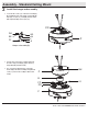
Assembly - Standard Ceiling Mount 10 Install the lampshade □ Place the lampshade (H) into the purification assembly (G) aligning the four flat areas on the flange top of the lampshade (H) with the four raised dimples in the purification assembly (G). □ Turn the shade (H) clockwise until it stops. G H 19 HAMPTONBAY.COM Please contact 1-855-HD-HAMPTON for further assistance.
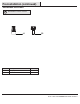
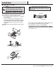
Operation Installing the batteries CAUTION: Do not use with a wall light dimmer switch. NOTE: The battery will weaken with age and should be replaced before leaking takes place as this will damage the remote control. Dispose of the used battery properly and keep the battery out of the reach of children. □ Remove the battery cover by pressing on the arrow and sliding the cover off. □ Install two 1.5V AAA batteries (S). □ Replace the battery cover on the remote control. S 1.
Operation 3. Description of the remote control functions NOTE : Press and hold the button Button ON/OFF Forward/reverse Purification level for 3 seconds to reset the filter time. Ceiling fan level Function Description 1. Press the button in the standby state to enter the power-on state. 2. Press the button in the power-on state to switch the ceiling fan, purification and lighting functions to the standby state at the same time.
Care and Cleaning WARNING: Make sure the power is off before cleaning your fan. □ Because of the fan’s natural movement, some connections may become loose. Check the support connections, brackets, and blade attachments twice a year. Make sure they are secure. It is not necessary to remove the fan from the ceiling. □ Clean your fan periodically to help maintain its new appearance over the years.
Troubleshooting Problem Solution The fan will not start. □ □ Check the main and branch circuit fuses or breakers. Check the line wire connections to the fan and switch wire connections in the switch housing. The fan is noisy. □ □ □ □ □ Ensure all motor housing screws are snug. Ensure the screws that attach the fan blade bracket to the motor hub are tight. Ensure the wire nut connections are not rattling against each other or the interior wall of the switch housing.
® Questions, problems, missing parts? Before returning to the store, call Hampton Bay Customer Service 8 a.m. - 7 p.m., EST, Monday - Friday, 9 a.m. - 6 p.m., EST, Saturday 1-855-HD-HAMPTON HAMPTONBAY.COM Retain this manual for future use.