
Architect and Engineering Manual


12
COMPONENTS & INSTALLATION
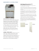
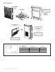
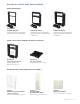
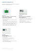
REMOTE THERMOSTAT
Z
oneline® Vertical units
are
controlled by a wall-mounted
thermostat. GE Appliances offers
a complete line of thermostats to
interface with the units, or most
24-VAC thermostats may be used.
Low-voltage wiring connections are made to the 8-pin
harness included with each unit. This harness allows
for a single-point thermostat connection to simplify
chassis removal and reinstallation. See diagram below
for terminal designations.
If a non–GE Appliances thermostat is used, the
compatibility of the thermostat with the unit is the
responsibility of the installer. The unit has an integral
transformer, and no external voltage or transformer
may be used.
Maximum wiring length and wire size: AWG 18 up to
66 feet; AWG 20 up to 66 feet; AWG 24 up to 40 feet.
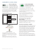
ENERGY MANAGEMENT
GE Appliances also offers the
RAK180W1 universal thermostat
that provides occupancy-sensing
energy management.
The thermostat works on single-stage or two-stage
heating systems and operates on a DC or AC signal.
The energy management setup can work on a room-by-
room basis or it can be upgraded with a network controller
for full site management.
Power to the thermostat can be via batteries or a
two-wire connection from the Zoneline Vertical
chassis. Command control signals are all conducted
via wireless communication.
For proper wireless communication, the transmitter
control card must be located on top of the Zoneline
Vertical chassis and NOT inside the metal cover.
DUCTWORK & SUPPLY REGISTERS—
FIELD SUPPLIED
Ductwork and supply registers are mentioned here as
System Essential Components, because they are necessary
to complete the installation. These components are field
supplied per the HVAC engineer’s design.
ELECTRICAL INFORMATION—GENERAL
Zoneline Single Packaged Vertical air conditioners are to be
connected to a single-phase 60 hertz power source. Units
with the voltage designator “D" in the 8th character of the
model number may be operated on either nominal 230-
volt or 208-volt power. Units with the voltage designator
“E" in the 8th character of the model number are to be
operated on nominal 265-volt power (A.K.A. 277-volt
power). For all installations, feeder, sub-feeder, branch
circuit and electrical protective devices must conform to
all local codes. In the absence of a local code, the National
Electrical Code should be followed.
Each unit should be installed on a single branch circuit.
More than one unit per branch circuit is not recommended.
All wiring must conform to local electrical regulations and
codes. When in doubt, consult the National Electrical Code.
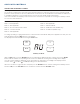
Black-C-Common
White-W-AUXHeat
Yellow-Y-Compressor
Green-GH-HighFan
Tan-GL-LowFan
Red-R-24VAC
BLUE-Not used
on AZ95E models
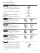
THERMOSTAT WIRING DIAGRAM
Preliminary specifications. Subject to change.
Thermostat Harness
Black -C- Common
White -W- AUXHeat
Yellow -Y-Compressor
Blue -not used
on AZ45 Series
Green -GH- HighFan
Tan -GL- LowFan
Red -R- 24VAC
Zoneline Thermostat
Connector