Installation Over the Range Instructions Microwave Oven BEFORE YOU BEGIN Read these instructions completely and carefully. • IMPORTANT – Save these • IMPORTANT – Observe all • Note to Installer – Be sure to leave these instructions for local inspector’s use. governing codes and ordinances. instructions with the Consumer. English/Spanish Note to Consumer – Keep these instructions for future reference.
Installation Instructions This is the safety alert symbol. This symbol alerts you to potential hazards that can kill or hurt you and others. All safety messages will follow the safety alert symbol and the word “DANGER”, “WARNING”, or “CAUTION”. These words are defined as: DANGER Indicates a hazardous situation which, if not avoided, will result in death or serious injury. WARNING Indicates a hazardous situation which, if not avoided, could result in death or serious injury.
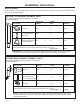
Installation Instructions HOOD EXHAUST NOTE: Read these next two pages only if you plan to vent your exhaust to the outside. If you plan to recirculate the air back into the room, proceed to page 11. OUTSIDE TOP EXHAUST (EXAMPLE ONLY) The following chart describes an example of one possible ductwork installation. EQUIVALENT NUMBER LENGTH x USED = LENGTH DUCT PIECES Roof Cap 24 Ft. x (1) = 24 Ft. 12 Ft. x (1) = 12 Ft. 12 Ft.
Installation Instructions NOTE: If you need to install ducts, note that the total duct length of 31⁄4″ x 10″ rectangular or 6″ diameter round duct should not exceed 140 equivalent feet. Outside ventilation requires a HOOD EXHAUST DUCT. Read the following carefully. NOTE: It is important that venting be installed using the most direct route and with as few elbows as possible. This ensures clear venting of exhaust and helps prevent blockages.
Installation Instructions DAMAGE – SHIPMENT INSTALLATION • I f the unit is damaged in shipment, return the unit to the store in which it was bought for repair or replacement. • If the unit is damaged by the customer, repair or replacement is the responsibility of the customer. • If the unit is damaged by the installer (if other than the customer), repair or replacement must be made by arrangement between customer and installer.
Installation Instructions TOOLS YOU WILL NEED Pencil #1 and #2 Phillips screwdriver Carpenter square (optional) Ruler or tape measure and straight edge Scissors (to cut template, if necessary) Tin snips (for cutting damper, if required) Electric drill with 3⁄16″, 7⁄16″, 1⁄2″ and 5⁄8″ drill bits Saw (saber, hole or keyhole) Gloves Stud finder Level Safety goggles MOUNTING SPACE *13″ max. 16-1⁄2″ 30″ 2″ 66″ or more from the floor to the top of the oven 6 30″ min.
Installation Instructions 1 PLACEMENT OF THE MOUNTING PLATE A. REMOVING THE MICROWAVE OVEN FROM THE CARTON B. FINDING THE WALL STUDS 1 Remove the installation instructions, filters, glass tray, mounting plate, and the small hardware bag. Do not remove the foam protecting the front of the oven. Fold back all 4 carton flaps fully against carton 2 sides. Then carefully roll the oven and carton over onto the top side. The oven should be resting in the foam.
Installation Instructions C DETERMINING MOUNTING PLATE LOCATION UNDER YOUR CABINET Plate Position – beneath flat bottom cabinet Plate Position – beneath framed recessed cabinet bottom 30” to Cooktop Draw a vertical line on the wall at the center of the 30” wide space. Tape the Rear Wall Template onto the wall matching the centerline and touching the bottom of the cabinet Plate Position – beneath recessed bottom cabinet with front overhang.
Installation Instructions D MARKING THE MOUNTING HOLES OPTION 1: USE PAPER REAR WALL TEMPLATE 30” This Rear Wall Template serves to position the bottom mounting plate and to locate the horizontal exhaust outlet. 1. Use a level to check that the template is positioned accurately. 2. Locate and mark at least one stud on the left or right side of the centerline. NOTE: It is important to use at least one wood screw mounted firmly in a stud to support the weight of the microwave.
Installation Instructions D MARKING THE MOUNTING HOLES OPTION 2: USE METAL BRACKET AS TEMPLATE NOTE: Refer to step C “DETERMINING MOUNTING PLATE LOCATION UNDER YOUR CABINET on page 8 for aligning instructions. STEP 1: Draw a vertical line on the wall at the center of the 30” space. STEP 4: Installer uses a level to draw a horizontal line that connects the two marks made with the stamped slot in the bracket. Horizontal line B D C A STEP 2: Installer uses bracket to make 2 marks.
Installation Instructions INSTALLATION TYPES 2 This microwave oven is designed for adaptation to the following three types of ventilation: A. Recirculating (Non-Vented Ductless) B. Outside Top Exhaust (Vertical Duct) C. Outside Back Exhaust (Horizontal Duct) A RECIRCULATING (NON-VENTED DUCTLESS) (Choose A, B or C) NOTE: Select the type of ventilation required for your installation and proceed to that section.
Installation Instructions RECIRCULATING A (Non-Vented Ductless) INSTALLATION OVERVIEW A1. Attach Mounting Plate to Wall A2. Prepare Top Cabinet A3. Check Blower Orientation A4. Adapting Microwave Blower For Recirculation A5. Mount the Oven A6. Installing The Charcoal Filter OPTION 2 3/8" TO EDGE STEP 1: Installer uses bracket to make 2 marks.
Installation Instructions A3. CHECK BLOWER MOTOR ORIENTATION The blower fan blade opening should be facing the front of the microwave. You will have to remove the top cover plate to check the fan blade orientation. If the fan opening is already facing the front of the microwave, skip to step A5. Otherwise, continue to Step A4 to adjust the fan motor orientation. 4 Roll the blower unit 90° so that fan blade openings are facing toward the front of the oven. BEFORE: Fan Blade Openings Facing Up A4.
Installation Instructions A4. ADAPTING BLOWER FOR RECIRCULATION (continued) 5 Place the blower unit back into the opening. CAUTION Do not pull or stretch the blower unit wiring. Make sure the wires are not pinched. 6 Replace blower motor screws removed in Step 2. Slide cover plate into position on the back of the unit. Replace blower plate and screws removed in Step 1. Attach second cover plate on blower plate (including one screw).
Installation Instructions A4. MOUNT THE OVEN (continued) 3 Attach the oven to the top cabinet by inserting 2 self-aligning screws through outer top cabinet holes. Turn two full turns on each screw. Be sure to keep power cord tight. Be careful not to pinch the cord, especially when mounting flush to bottom of cabinet. A6. W HEN REPLACING THE CHARCOAL FILTER If the model is not vented to the outside, the air will be recirculated through a disposable charcoal filter that helps remove smoke and odors.
Installation Instructions B OUTSIDE TOP EXHAUST (Vertical Duct) INSTALLATION OVERVIEW B1. Attach Mounting Plate to Wall B2. Prepare Top Cabinet B3. Check Motor Orientation B4. Adapting For Outside Ventilation B5. Assemble and Install Adaptor B6. Mount the Microwave B7. Adjust The Exhaust Adaptor B8. Connecting Duckwork OPTION 2 3/8" TO EDGE STEP 1: Installer uses bracket to make 2 marks.
Installation Instructions B2 U SE TOP CABINET TEMPLATE FOR PREPARATION OF TOP CABINET You need to drill holes for the top support screws, a hole large enough for the power cord to fit through, and a cutout large enough for the exhaust adaptor. 2 Slide the blower plate from under its retaining flange and lift it off. Remove the cover plate installed on the back.
Installation Instructions B4. A DAPTING BLOWER FOR OUTSIDE VENTILATION (continued) 5 Place the blower unit back into the opening. CAUTION Do not pull or stretch the blower unit wiring. Make sure the wires are not pinched. 3 Attach the exhaust adaptor to the blower plate with the two bronze metal screws provided. Make sure that the damper pivots easily before mounting oven. You will need to make adjustments to assure proper alignment with your house exhaust duct after the oven is installed. B6.
Installation Instructions B6. MOUNT THE OVEN (continued) Cabinet Front Cabinet Bottom Shelf Filler Block Equivalent to Depth of Cabinet Recess B7. ADJUST THE EXHAUST ADAPTOR Open the top cabinet and adjust the exhaust adaptor to connect to the house duct. Damper Back of Oven Self-Aligning Screw Oven Top Attach the oven to the top cabinet by inserting 2 self-aligning screws through outer top cabinet holes. Turn two full turns on each screw. Be sure 3 to keep power cord tight.
Installation Instructions OUTSIDE BACK EXHAUST (Horizontal Duct) C INSTALLATION OVERVIEW C1. Prepare Rear Wall C2. Attach Mounting Plate to Wall C3. Prepare Top Cabinet C4. Adjust Blower C5. Mount The Oven OPTION 2 3/8" TO EDGE STEP 1: Installer uses bracket to make 2 marks. First 12" OPTION 1 NOTE: IT IS VERY IMPORTANT TO READ AND FOLLOW THE DIRECTIONS IN THE INSTALLATION INSTRUCTIONS BEFORE PROCEEDING WITH THIS REAR WALL TEMPLATE.
Installation Instructions C3. U SE TOP CABINET TEMPLATE FOR PREPARATION OF TOP CABINET You need to drill holes for the top support screws and a hole large enough for the power cord to fit through. DAPTING BLOWER FOR C4. A OUTSIDE BACK EXHAUST 1 Remove and save the two screws that hold the blower plate in place. Slide blower plate from under its retaining flange. Remove the cover plate installed on the back.
Installation Instructions 5 Locate the two “knockout” plates, on the rear oven panel, near the top of the oven. Using tin snips, carefully cut the web area from the two holes side-by-side (that secure the knockouts to the oven). Cut all four webs on both rear knockouts; this will allow the ventilation fan airflow to exhaust out the rear of the oven. CAUTION Be sure to trim the sharp edges from the openings after removing the knockout plates.
Installation Instructions Cabinet Front Cabinet Bottom Shelf Filler Block Equivalent to Depth of Cabinet Recess Self-Aligning Screw Oven Top 3 Attach the oven to the top cabinet by inserting 2 self-aligning screws through outer top cabinet holes. Turn two full turns on each screw. Be sure to keep power cord tight. Be careful not to pinch the cord, especially when mounting flush to bottom of cabinet. 4 Tighten the two screws to the top of the oven completely.
Installation Instructions BEFORE YOU USE YOUR MICROWAVE 1. Make sure the microwave oven has been installed according to instructions. 2. emove all packing material from the R microwave oven. 3. Install turntable and ring in cavity. 4. Replace house fuse or turn breaker back on. 6. Read the Owner’s Manual. 7. KEEP INSTALLATION INSTRUCTIONS FOR THE LOCAL INSPECTOR’S USE. Plug power cord into a dedicated 15- to 5. 20-amp electrical outlet.