
GE RAK204 Installation Manual


31-5000401 Rev. 0 03-19 GEA
Tools Needed
• 5/16” nut driver
• Pliers
• Slotted screwdriver
Important Notes
• This unit must be properly grounded.
• Read this instruction before installing the sub-base to the
molded or metal case.
CAUTION
The sub-base should be assembled to the
case before securing the case in the wall.
CAUTION
Electrical power must be disconnected
before installing the sub-base.
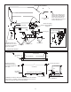
Electrical Requirements :
1. Electrical wiring may enter the sub-base through
any of the knockout holes provided in the sub-base
bottom or rear.
2. Refer to the unit nameplate for branch circuit
requirements.
3. All wiring should be done in accordance with the local
electrical codes and regulations.
4. Not approved for aluminum wire application.
5. If electrical wiring is placed in or against the sub-
base enclosure, the sub-base must be grounded.
Grounding holes have been provided in the back
surface of the enclosure. See diagram. Green
grounding screws and securing nuts are included.
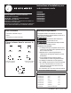
Parts included in bag with Sub-Base
Installation Instructions
for your new
RAK204U
RAK204D15C
RAK204D20C
RAK204D30C
RAK204E15C
RAK204E20C
RAK204E30C
Sub-Base
Before you begin - Read these instructions completely
and carefully. IMPORTANT – OBSERVE ALL
GOVERNING CODES AND ORDINANCES. Note to
Installer – Be sure to leave these instructions with the
Consumer. Note to Consumer – Keep these instructions
with your Owner’s Manual for future reference.
Type A
10 required
Type D
2 mounting clips for
metal case
Chaseway and
cover
Type E
2 mounting clips for
molded case
4 nuts
Type B
2 required
Type C
2 required
Kit Number Description
RAK204U NON-ELECTRICAL SUB-BASE
RAK204E15C 265 V 15 A
RAK204E20C 265 V 20 A
RAK204E30C 265 V 30 A
RAK204D15C 230/208 V 15 A
RAK204D20C 230/208 V 20 A
RAK204D30C 230/208 V 30 A
RAK4002D JUNCTION BOX