With QuietBoost™ Blower VENTED RANGE HOODS SAFETY INFORMATION . . . . . . . . . . . . .3 USING THE HOOD Controls . . . . . . . . . . . . . . . . . . . . . . . . . . . . . . . . . .5 Wi-Fi Connect . . . . . . . . . . . . . . . . . . . . . . . . . . . . 6 Filters . . . . . . . . . . . . . . . . . . . . . . . . . . . . . . . . . . . .7 CARE AND CLEANING OWNER’S MANUAL & INSTALLATION INSTRUCTIONS UVW8304 UVW8364 Surfaces . . . . . . . . . . . . . . . . . . . . . . . . . . . . . . . . . .8 Lights . . . .
THANK YOU FOR MAKING GE APPLIANCES A PART OF YOUR HOME. Whether you grew up with GE Appliances, or this is your first, we’re happy to have you in the family. We take pride in the craftsmanship, innovation and design that goes into every GE Appliances product, and we think you will too. Among other things, registration of your appliance ensures that we can deliver important product information and warranty details when you need them. Register your GE appliance now online.
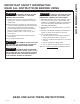
WARNING TO REDUCE THE RISK OF FIRE, ELECTRIC SHOCK OR INJURY TO PERSONS, OBSERVE THE FOLLOWING: A. Use this unit only in the manner intended by the manufacturer. If you have questions, contact the manufacturer. B. Before servicing or cleaning unit, switch power off at service panel and lock the service disconnecting means to prevent power from being switched on accidentally.
SAFETY INFORMATION IMPORTANT SAFETY INFORMATION READ ALL INSTRUCTIONS BEFORE USING WARNING TO REDUCE THE RISK OF A C. When cutting or drilling into wall or ceiling, do not damage electrical wiring and other hidden utilities. RANGE TOP GREASE FIRE: D. Ducted fans must always be vented to the outdoors. A. Never leave surface units unattended at high settings. Boilovers cause smoking and greasy spillovers that may ignite. Heat oils slowly on medium settings. E.
1 3 2 4 Fan Settings 2ႇ Low Delay Oႇ Hold 3 Sec WiFi Pairing Med High Light WiFi Boost Chef Connect To Pair Hold 3 Sec Hold 3 Sec 7 1. Rangehood Control Panel: The control panel is located under the front edge of the canopy. The position and function of each control button are noted below. 2. Fan On/Off: On/Off switch for the fan. The fan can be operated by pressing any of the fan setting buttons.
USING THE HOOD: Wi-Fi Connect Wi-Fi Connect Connecting your Wi-Fi Connect Enabled hood (on some models) Your GE Appliances hood is designed to provide you with two-way communication between your appliance and smart device. By using the GE Appliances Wi-Fi Connect features, you will be able to control essential hood operations such as fan speed, light functions, delay off and filter notification using your smartphone or tablet. This device complies with part 15 of the FCC Rules.
Be sure the circuit breaker is off and all surfaces are cool before cleaning or servicing any part of the vent hood. Grease Filter The filter traps grease released by foods from cooking. The filters must ALWAYS be in place when the hood is in use. The grease filters are dishwasher-safe and should be cleaned every month, or as needed. To remove: Pull downward on the filter lock to release the filter. To replace: Fit the tabs at the bottom of the filter behind the ledge of the filter opening.
CARE AND CLEANING: Surfaces / Lights 8 Surfaces Stainless Steel Surfaces (on some models) Do not use a steel wool pad; it will scratch the surface. To clean the stainless steel surface, use warm sudsy water or a stainless steel cleaner or polish. Always wipe the surface in the direction of the brush line. Follow the cleaner instructions for cleaning the stainless steel surface. Cleaners with oxalic acid such as Bar Keepers Friend Soft Cleanser™ will remove surface rust, tarnish, and small blemishes.
Range Hoods “If you have questions, call GE Appliances at 800.GE.CARES (800.432.2737) or visit our website at: GEAppliances.com” BEFORE YOU BEGIN Read these instructions completely and carefully. Ŷ Ŷ IMPORTANT — Save these instructions for local inspector’s use. IMPORTANT — Observe all governing codes and ordinances. Ŷ Note to Installer – Be sure to leave these instructions with the Consumer. Ŷ Note to Consumer – Keep these instructions for future reference.
INSTALLATION PREPARATION Installation Preparation PRODUCT DIMENSIONS TOOLS AND MATERIALS REQUIRED (NOT SUPPLIED) 30” Models Requires a 30” opening. Safety glasses Pencil and tape measure 10" 16-1/2" Phillips screwdriver with at least 6" shank 21" 30" Level Wire cutter/stripper 36” Models Requires a 36” opening.
PLAN THE INSTALLATION CAUTION To reduce risk of fire and to PARTS PROVIDED Locate the parts packed with the hood. properly exhaust air, be sure to duct the air outside. Do not vent exhaust air into spaces within walls or ceilings or into attics, crawl spaces, or garages.
INSTALLATION PREPARATION Installation Preparation DUCT COVER REQUIREMENTS INSTALLATION DIMENSIONS Duct Cover Kit must be purchased separately. We recommend that the vent hood and duct cover (if used) be on site before final framing and wall finishing. This will help to accurately locate studs, ductwork, and electrical service. The hood duct covers can be adjusted for different ceiling heights depending on the distance between the bottom of the hood and the cooktop (distance X).
INSTALLATION HEIGHT TABLE CX10DC9SPSS CX12DC9SPSS High Ceiling Duct Cover up to 10 ft. High Ceiling Duct Cover up to 12 ft. Installation Over Gas Range Ceiling Height (ft./in.) Recirculation Installation Height Vented Installation Height (Recirculation holes hidden) Installation Over Electric Range Recirculation Installation Height Vented Installation Height (Recirculation holes hidden) Installation Over Gas Range Ceiling Height (ft./in.
INSTALLATION PREPARATION Installation Preparation ADVANCE PLANNING Duct Install Planning Ŷ This hood is designed to be vented vertically through the ceiling with a 8” round duct or backwall using an 90º elbow and 8” round duct. Vent system can terminate either through the roof RU WKH ZDOO 7R YHQW WKURXJK D ZDOO D HOERZ LV needed and installed immediately above the hood. Roof Cap Ŷ Use metal ductwork only. Ŷ Plan the route for venting exhaust to the outdoors.
INSTALLATION PREPARATION Installation Preparation NEW CONSTRUCTION, PRE-PLANNING, OR REMODELING NOTE: For existing construction, skip to the section below. Ŷ For ducted installation through the top, the 8" diameter hole for the duct in the ceiling must be centered 6-1/4" away from the finished rear wall in the installation space Ŷ The hood junction box knockout is located 10-1/2" to the left from center of the hood. Ensure enough wire length is available to make electrical connection.
INSTALLATION PREPARATION Installation Preparation DETERMINE HOOD, DUCTWORK AND WIRING LOCATIONS (Cont.) House Wiring Location: • The junction box is located inside the hood body on the left side. See Illustrations for hood knockout locations. House wiring may enter the junction box from the rear or the top of the hood at the right side. To route house wiring through the ceiling,soffit, or cabinet: • Cut a hole approximately 1-1/4" dia.
1 INSTALL HOOD SUPPORT 1 INSTALL HOOD SUPPORT (cont) IMPORTANT: Framing must be capable of supporting 100 lbs. • Locate at least 2 vertical studs for the installation bar by tapping drywall with a hammer or use a stud finder. • Level the installation bar and center left to right above the marked line. Hold bar against the wall. • Install wall anchors (C) by tapping the anchors with a hammer to seat the teeth of the flanges into the wall. This keeps anchor from rotating.
INSTALLATION INSTRUCTIONS Installation Instructions 4 (Alternate Mounting Method) INSTALL HOOD TO SOFFIT OR CABINET SKIP THIS STEP IF USING WALL MOUNTING METHOD IMPORTANT: Soffit or cabinet framing must be capable of supporting 100 lbs. Back Wall 2-3/4" 10" When necessary the hood may be installed so that it is supported by the soffit or cabinet. A • The soffit should be constructed with 2"x4"s. • Use a level to draw the cooktop or range center line.
5 INSTALL MOTOR 6 CONNECT ELECTRICAL 1. Align the motor exhaust with the top damper as shown in figure below. Verify that power is tured off at the source. WARNING If house wiring is not 2-wire with a ground wire, a ground must be provided by the installer. When house wiring is aluminum, be sure to use UL approved anti-oxidant compound and aluminum-to-copper connections. 2. Secure the motor to motor mounting plate using screws (D). • Remove junction box cover.
INSTALLATION INSTRUCTIONS Installation Instructions 7 CONNECT DUCTWORK A. Vented Installation B. Recirculation (non-vented) Installation • Connect the house ducting to the top damper as shown in image below. NOTE: A recirculation duct (WB34X30519), and Charcoal Filter (UXCF91), are not included with the hood and are necessary for recirculation installation. • Seal all connections with duct tape. 1. Attach the recirculation duct to the duct cover mounting bracket with screws provided. 2.
8 INSTALL DUCT COVERS • Duct Cover Accessories are available at GEApplianceparts.com or by calling 877.959.8688. See Accessories on page 27. 9 INSTALL FILTERS • Follow instructions on page 7 “Filters” to install or remove filters. • Follow instructions included with the duct cover accessory to install duct covers. Filter Lock 49-2000708 Rev.
INSTALLATION INSTRUCTIONS Installation Instructions MAKE UP AIR TECHNOLOGY This operation must be performed by a qualified technician or installer. Note to Installers and Inspectors : This product comes equipped with a simple installation feature that limits maximum CFM levels in order to comply with certain local codes or regulations. This installation method may not be necessary for all installations, please refer to your codes for further guidelines.
Notes 49-2000708 Rev.
Notes 24 49-2000708 Rev.
Save time and money! Review the charts on the following pages first and you may not need to call for service. Problem Possible Cause What To Do Fan/Light does not operate when button is turned ON A house fuse may be blown or a circuit breaker tripped. Replace fuse or reset circuit breaker. Loud or abnormal airflow noise Wrong duct size used in installation. This hood requires 8” ducting to perform optimally. Using smaller duct pipe will cause reduced venting.
LIMITED WARRANTY GE Appliances Vented Range Hood Warranty GEAppliances.com All warranty service is provided by our Factory Service Centers, or an authorized Customer Care® technician. To schedule service online, visit us at www.geappliances.com/service_and_support/, or call GE Appliances at 800.GE.CARES (800.432.2737). Please have your serial number and your model number available when calling for service. Servicing your appliance may require the use of the onboard data port for diagnostics.
Looking For Something More? GE Appliances offers a variety of accessories to improve your cooking and maintenance experiences! Refer to the Consumer Support page for phone numbers and website information.
CONSUMER SUPPORT Consumer Support GE Appliances Website Have a question or need assistance with your appliance? Try the GE Appliances Website 24 hours a day, any day of the year! You can also shop for more great GE Appliances products and take advantage of all our on-line support services designed for your convenience. In the US: GEAppliances.
CAMPANAS DE COCINA CON VENTILACIÓN Con Extractor QuietBoost™ INFORMACIÓN DE SEGURIDAD . . . .3 USO DE LA CAMPANA Controles . . . . . . . . . . . . . . . . . . . . . . . . . . . . . . . . . 5 Conexión Wi-Fi . . . . . . . . . . . . . . . . . . . . . . . . . . . .6 Filtros . . . . . . . . . . . . . . . . . . . . . . . . . . . . . . . . . . . . 7 CUIDADO Y LIMPIEZA MANUAL DEL PROPIETARIO Y INSTALACIÓN UVW8304 UVW8364 Superficies . . . . . . . . . . . . . . . . . . . . . . . . . . . . . . . . 8 Luces . .
GRACIAS POR HACER QUE GE APPLIANCES SEA PARTE DE SU HOGAR. Ya sea que haya crecido usando GE Appliances, o que ésta es su primera vez, nos complace tenerlo en la familia. Sentimos orgullo por el nivel de arte, innovación y diseño de cada uno de los electrodomésticos de GE Appliances, y creemos que usted también. Entre otras cosas, el registro de su electrodoméstico asegura que podamos entregarle información importante del producto y detalles de la garantía cuando los necesite.
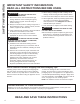
ADVERTENCIA PARA REDUCIR EL RIESGO DE INCENDIO, DESCARGA ELÉCTRICA O LESIONES A PERSONAS, CUMPLA CON LOS SIGUIENTES PUNTOS: A. Utilice esta unidad sólo de la manera concebida por el fabricante. Si tiene alguna pregunta, comuníquese con el fabricante. B. Antes de realizar reparaciones o limpiar la unidad, desconecte la energía del panel de servicio y bloquee los medios de desconexión para evitar el accionamiento de la energía de manera accidental.
INFORMACIÓN DE SEGURIDAD INFORMACIÓN IMPORTANTE DE SEGURIDAD LEA TODAS LAS INSTRUCCIONES ANTES DE USAR ADVERTENCIA PARA REDUCIR EL RIESGO DE UN INCENDIO DE GRASA SOBRE UNA ESTUFA: A. Nunca deje unidades de superficie desatendidas en configuraciones de calor elevadas. Los alimentos que hierven y se derraman provocan humo y derrames grasosos que pueden prenderse fuego. Caliente los aceites lentamente en configuraciones bajas o medias. B.
1 2 3 4 Fan Settings 2ႇ Low Delay Oႇ Hold 3 Sec WiFi Pairing Med 7 1. Panel de Control de la Campana Extractora: 2. 3. El panel de control está ubicado debajo del extremo frontal de la base. La posición y función de cada botón del control figura a continuación. Ventilador Encendido/ Apagado: Interruptor de apagado del ventilador. El ventilador puede ser usado presionando cualquiera de los botones de configuración del ventilador.
USO DE LA CAMPANA: Conexión Wi-Fi Conexión Wi-Fi Conecte su campana con Conexión Habilitada de Wi-Fi (en algunos modelos) Su campana de GE Appliances está diseñado para brindarle una comunicación recíproca entre su electrodoméstico y el dispositivo inteligente. Al usar las funciones de Wi-Fi Connect de GE Appliances, usted podrá controlar funciones esenciales de la campana tales como la velocidad del ventilador, retraso del apagado y notificaciones de filtro utilizando su teléfono inteligente o tablet.
Asegúrese de que la energía eléctrica esté apagada y que todas las superficies estén frías antes de limpiar o arreglar cualquier pieza de la campana de ventilación. Filtro de grasa El filtro atrapa la grasa liberada por las comidas durante su cocción. Filtro debe estar SIEMPRE en su lugar cuando la campana esté en funcionamiento. El filtro de grasa es apto para lavavajillas y debe limpiarse cada mese, o según sea necesario.
CUIDADO Y LIMPIEZA: Superficies / Lámparas 8 Superficies Superficies de acero inoxidable (en algunos modelos) No utilice almohadillas de acero porque rayan la superficie. Para limpiar la superficie de acero inoxidable, utilice agua tibia jabonosa o un limpiador o lustrador de acero inoxidable. Siempre limpie la superficie en dirección de la veta. Siga las instrucciones del producto para limpiar la superficie de acero inoxidable.
Campanas para Cocinas “Ante cualquier duda, llame a GE Appliances al 800.GE.CARES (800.432.2737) o visite nuestro sitio Web en: GEAppliances.com” ANTES DE COMENZAR Lea estas instrucciones por completo y con detenimiento. Ŷ IMPORTANTE — Guarde estas instrucciones para el uso de inspectores locales. Ŷ IMPORTANTE — Cumpla con todos los códigos y ordenanzas vigentes. Ŷ Nota al instalador – Asegúrese de dejar estas instrucciones con el Consumidor.
PREPARACIÓN PARA LA INSTALACIÓN Preparación para la instalación HERRAMIENTAS Y MATERIALES REQUERIDOS (NO SUMINISTRADOS) PRODUCTO Modelos de 30” Requiere una abertura de 30” Gafas de seguridad Lápiz y cinta métrica 10" 16-1/2" Destornillador Phillips con un vástago de por lo menos 6”.
PLAN DE INSTALACIÓN ADVERTENCIA A fin de reducir riesgos de incendios y para que el aire salga de forma apropiada, asegúrese de que el aire sea conducido hacia fuera.No ventile el aire de la salida hacia espacios dentro de paredes o cielorrasos o áticos, espacios muy bajos o garajes. PIEZAS PROVISTAS: Ubique las piezas embaladas con la campana.
PREPARACIÓN PARA LA INSTALACIÓN Preparación para la instalación REQUISITOS SOBRE LA TAPA DEL CONDUCTO Los kits para la tapa del conducto se deberán adquirir aparte. Le recomendamos que la campana de ventilación y la tapa del conducto (de ser usadas) estén en sus posiciones antes del enmarcado final y el acabado de pared. Esto ayudará a ubicar los montantes, el conducto y el cableado eléctrico de forma precisa.
TABLA DE ALTURAS DE INSTALACIÓN CX10DC9SPSS CX12DC9SPSS Tapa del Conducto del Cielorraso de hasta 10 pies Altura del Cielorraso (pies/ pulg.
PREPARACIÓN PARA LA INSTALACIÓN Preparación para la instalación PLANIFICACIÓN PREVIA Planificación para la Instalación con Conducto Ŷ Esta campana fue diseñada para ventilar de forma vertical a través del cielorraso con un conducto cilíndrico de 8” o a través de una pared trasera usando un codo de 90° y un conducto cilíndrico de 8". Ŷ Determine la ubicación exacta de la campana de ventilación. Ŷ Planifique el recorrido de la salida de ventilación hacia el exterior.
NUEVA CONSTRUCCIÓN, PLANIFICACIÓN PREVIA O REMODELACIÓN NOTA: Para acceder a las instrucciones existentes, vaya a la siguiente sección. Ŷ Para una instalación con conducto a través de la parte superior, el agujero para el conducto del cielorraso deberá estar centrado a una distancia de 6 ¼” de la pared trasera terminada en el espacio de instalación. Ŷ El tablero de la caja de empalmes de la campana está ubicado a 10 ½” hacia la izquierda desde el centro de la campana.
PREPARACIÓN PARA LA INSTALACIÓN 16 Preparación para la instalación DETERMINE LAS UBICACIONES DE LA CAMPANA, EL CONDUCTO Y EL CABLEADO (Cont.) Ubicación del Cableado Hogareño: • La caja de empalmes se encuentra ubicada dentro del cuerpo de la campana sobre el lado izquierdo. Consulte las ilustraciones para conocer las ubicaciones del tablero de la campana. El cableado hogareño podrá ingresar a la caja de empalmes desde la parte trasera o desde la parte superior de la campana, sobre el lado izquierdo.
1 INSTALACIÓN DEL SOPORTE DE LA CAMPANA 1 INSTALACIÓN DEL SOPORTE DE LA CAMPANA (Cont.) IMPORTANTE: El marco deberá poder sostener 100 lbs • Ubique mínimamente 2 vigas verticales para la barra de instalación, golpeando la pared de yeso con un martillo o usando un detector de vigas. • Nivele la barra de instalación y centre de izquierda a derecha sobre la línea marcada. Sostenga la barra contra la pared.
INSTRUCCIONES DE INSTALACIÓN Instrucciones de Instalación 4 (Método Alternativo de Montaje) INSTALE LA CAMPANA EN EL SOFITO O GABINETE Pared Trasera SALTEE ESTE PASO SI USARÁ UN MÉTODO DE MONTAJE DE PARED IMPORTANTE: El marco del sofito o gabinete deberán poder sostener 100 lbs. 2-3/4" 10" Cuando sea necesario, la campana podrá ser instalada de modo que sea sostenida por el sofito o gabinete. • El sofito deberá estar construido de vigas de 2”x4”.
5 INSTALE EL MOTOR 6 CONEXIÓN DE LA ELECTRICIDAD 1. Alinee la ventilación del motor con el regulador superior, como se muestra en la siguiente figura. Verifique que la corriente esté apagada en la fuente. ADVERTENCIA Si el cableado del hogar no tiene 2 cables con uno a tierra, el instalador deberá proveer una conexión a tierra. Cuando el cableado hogareño sea de aluminio, asegúrese de usar un compuesto antioxidante y conectores de aluminio a cobre aprobados por UL.
INSTRUCCIONES DE INSTALACIÓN Instrucciones de Instalación 7 CONECTE EL CONDUCTO A. Instalación de la Ventilación B. Instalación de la Recirculación (no ventilada) • Conecte el conducto hogareño al regulador superior, como se muestra en la siguiente imagen. NOTA: Un conducto de recirculación (WB34X30519) y un Filtro de Carbón (UXCF91) no se encuentran incluidos con la campana y son necesarios para la instalación de la recirculación. • Selle todas las conexiones con cinta para conductos. 1.
8 INSTALE LAS TAPAS DE LOS CONDUCTOS • Los Accesorios de la Tapa del Conducto están disponibles en GEApplianceparts.com o llamando al 877.959.8688. Consulte la sección de Accesorios en la página 27. • Siga las instrucciones incluidas con el accesorio de la tapa del conducto para instalar las tapas de conducto. 9 INSTALACIÓN DE LOS FILTROS • Siga las instrucciones de “Filtros” en la página 7 para instalar o retirar filtros. Bloqueo del Filtro 49-2000708 Rev.
INSTRUCCIONES DE INSTALACIÓN Instrucciones de Instalación TECNOLOGÍA DE REPOSICIÓN DE AIRE Esta operación deberá ser realizada por un técnico o instalador calificado. Nota para los Instaladores e Inspectores: Este producto está equipado con una función de instalación simple que limita los niveles máximos de CFM, a fin de cumplir con ciertos códigos o regulaciones locales.
¡Ahorre tiempo y dinero! Primero revise los cuadros que aparecen en las siguientes páginas y es posible que no necesite solicitar reparaciones. Problema Causas posibles Qué hacer El Ventilador/ la Luz no funciona cuando el botón está en ON (Encendido) El fusible puede haberse quemado o el interruptor decircuitos puede haber saltado. Cambie los fusibles o reconfigure el interruptor de circuitos. Ruido de flujo de aire muy elevado o anormal Tamaño de conducto incorrecto utilizado en la instalación.
GARANTÍA LIMITADA Garantía Limitada de la Cocina Eléctrica de GE Appliances GEAppliances.com Todo el servicio de garantía es provisto por nuestros Centros de Servicio de Fabricación, o un técnico autorizado de Customer Care®. Para programar una visita del servicio técnico a través de Internet, visítenos en www.geappliances.com/service_and_support/, o llame al 800.GE.CARES (800.432.2737). Cuando llame para solicitar el servicio, tenga los números de serie y modelo disponibles.
¿Busca Algo Más? GE Appliances ofrece una variedad de accesorios para mejorar sus experiencias de cocción y mantenimiento! Para acceder a números telefónicos e información de sitios Web, consulte la página de Soporte para el Consumidor.
SOPORTE PARA EL CONSUMIDOR Soporte para el Consumidor Sitio Web de GE Appliances ¿Desea realizar una consulta o necesita ayuda con su electrodoméstico? ¡Intente a través del Sitio Web de GE Appliances las 24 horas del día, cualquier día del año! Usted también puede comprar más electrodomésticos maravillosos de GE Appliances y aprovechar todos nuestros servicios de soporte a través de Internet, diseñados para su conveniencia. En EE.UU.: GEAppliances.