
Manual

GE
Preliminary Data Sheet
12A Digital SlimLynx
TM
: Non-Isolated DC-DC Power Modules
3Vdc –14.4Vdc input; 0.45Vdc to 5.5Vdc output; 12A Output Current
February 19, 2014 ©2014 General Electric Company. All rights reserved. Page 17
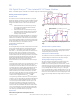
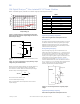
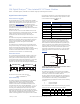
Synchronization
The module switching frequency can be synchronized to a
signal with an external frequency within a specified range.
Synchronization can be done by using the external signal
applied to the SYNC pin of the module as shown in Fig. 45,
with the converter being synchronized by the rising edge of
the external signal. The Electrical Specifications table
specifies the requirements of the external SYNC signal. If the
SYNC pin is not used, the module should free run at the
default switching frequency. If synchronization is not being
used, connect the SYNC pin to GND.
MODULE
SYNC
GND
+
─
Figure 45. External source connections to synchronize
switching frequency of the module.
Measuring Output Current, Output Voltage and Input
Voltage
Please see the Digital Feature Descriptions section.
Tunable Loop
TM
The module has a feature that optimizes transient response
of the module called Tunable Loop
TM
.
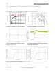
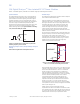
External capacitors are usually added to the output of the
module for two reasons: to reduce output ripple and noise
(see Figure 38) and to reduce output voltage deviations from
the steady-state value in the presence of dynamic load
current changes. Adding external capacitance however
affects the voltage control loop of the module, typically
causing the loop to slow down with sluggish response.
Larger values of external capacitance could also cause the
module to become unstable.
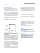
The Tunable Loop
TM
allows the user to externally adjust the
voltage control loop to match the filter network connected
to the output of the module. The Tunable Loop
TM
is
implemented by connecting a series R-C between the VS+
and TRIM pins of the module, as shown in Fig. 47. This R-C
allows the user to externally adjust the voltage loop
feedback compensation of the module.
Figure. 47. Circuit diagram showing connection of R
TUME
and C
TUNE
to tune the control loop of the module.
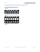
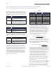
Recommended values of R
TUNE
and C
TUNE
for different output
capacitor combinations are given in Table 2. Table 2 shows
the recommended values of R
TUNE
and C
TUNE
for different
values of ceramic output capacitors up to 1000uF that
might be needed for an application to meet output ripple
and noise requirements. Selecting R
TUNE
and C
TUNE
according
to Table 2 will ensure stable operation of the module.
In applications with tight output voltage limits in the
presence of dynamic current loading, additional output
capacitance will be required. Table 3 lists recommended
values of R
TUNE
and C
TUNE
in order to meet 2% output
voltage deviation limits for some common output voltages
in the presence of a 6A to 12A step change (50% of full load),
with an input voltage of 12V.
Please contact your GE Critical Power technical
representative to obtain more details of this feature as well
as for guidelines on how to select the right value of external
R-C to tune the module for best transient performance and
stable operation for other output capacitance values.
VS+
MODULE
SIG_GND
TRIM
VOUT
RTune
CTune
RTrim
CO
GND