
User Manual


4
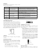
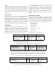
Figure 1. Three-wire maintained connections.
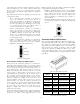
Figure 2. Two-wire maintained connections.
Figure 3. Three-wire and two-wire momentary connections.
Outputs
• Backplane outputs control up to 66 breakers
• One alarm relay output, NO/NC contacts, 24 Vac @
0.5 A
Device Addressing
• Set via DIP switch and jumpers, DIP switch MAC
address range: 0 to 99 per network segment
Physical Parameters
• Size – 10.765" x 6.070" x 2" (27.3 x 14.6 x 5.1 cm)
• Weight – 1 lb (454 gm)
Hardware Overview
Configuration
• 16-bit Processor
• 2 MB(16Mbit) flash memory (software loadable
firmware)
• 512 kB SRAM memory (for database)
• Database backup via nonvolatile flash memory
• Real-time clock with lithium battery for clock and
SRAM backup
• Visual LED status indication of the CPU
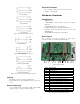
Board Layout
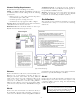
The controller is shown in Figure 4, with major
components indicated and identified in Table 1.
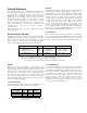
Figure 4. Lighting controller.
Letter Component
A Battery
B Switch inputs
C RS-232 port
D Ethernet port
E Address switch
F Input power from Class II transformer
G NET1 primary network connector
H BACnet/Modbus selector jumper
I Service port/Programmer connection
J NET2 subnet connector
K Analog input ports (3)
L Analog input configuration jumpers
M Local override input
N Analog output dry contact (NO/NC)
Table 1. Components on lighting controller board.
A
B C
D
E F G H I J K L
M
N