
User Manual


8
Default Database
The lighting controller is a BACNet-protocol Device. It
contains predefined objects to provide standard features
and functions of lighting control. These objects are
divided into logical groups: breakers (outputs), inputs,
lighting zones, scheduling, events, security, and device
information. These objects are specified to assign
breakers, schedule, lighting zones, and response to switch
inputs. The lighting controller can be configured as a
100% stand-alone device using, the real-time clock
calendar, or as a slave device, reacting to switch or
software inputs.
The default database contains approximately 600
predefined objects.
Breaker Outputs (BO1–66)
Controlling GE Remote-Operated Circuit Breakers
(ROCB) is the primary function of the lighting controller.
These breakers are represented in the database as control
objects. Breaker outputs and corresponding BACNet
objects and Modbus register values are listed in Table 4.
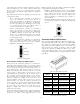
Breakers
The lighting controller supports 12-, 18-, 24-, 30-, 36-, and
42-circuit panels. Binary outputs (BO) are mapped to the
possible physical outputs of the lighting controller. Each
binary output has a breaker-override binary variable (BV)
referenced as the override input field, with a default
override time of 120 minutes. Commanding the breaker
override BV from
OFF to ON triggers the override
condition for the given binary output. The breaker
override menu in the programmer allows editing of the
breaker override BV values. Binary output objects that
have no physical remote-operated breaker attached enter
Fault mode and their reliability displays as Not Available.
These appear on the LCD display with an X.
Local Override
Each controller can be locally overridden by a switch input
or by accessing binary output BO67. This feature turns all
breakers
ON or OFF. Once the switch is deactivated, the
breakers remain in this state until commanded to change.
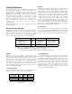
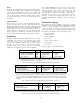
Description Type BACNet Object Modbus Register
Breakers (1–66)
• Output value
• Mode (auto/manual)
• Feedback status
RW
RW
RO
BO1–66
• PresentValue
• OutOfService
• Feedback
Fn 1/5/15, 001–066*
Fn 1/5/15, 201–266
Fn 2, 001–066
Breaker sweep (ON/OFF) RW BO67 Fn 1/5/15, 067
* The value in the Modbus register represents the binary output’s present value when read.
Writes occur at BACnet priority level 5 (critical equipment control). Writes are only
accepted if the ‘OutOfService’ flag is set for that particular output.
Table 4. Breaker outputs and corresponding BACNet object and Modbus register values.
Inputs
There are two classes of inputs: local and remote. The
lighting controller includes three analog Iputs and 16
standard switch inputs. The lighting controller also
supports up to four additional remote input modules,
increasing the switch input count to 66. Additionally,
there are three analog inputs on its main board (IP1–3)
represented by analog input objects (AI1–3). These inputs
allow additional inputs (such as photosensors) to be used
when controlling the lighting.
Local Analog Inputs
Analog input objects AI1 to AI3 refer to the inputs located
on the controller’s main board, as listed in Table 5.
Description Type
BACNet
Object
Modbus
Register
Analog input 1 RO AI1 Fn 4, 101
Analog input 2 RO AI2 Fn 4, 102
Analog input 3 RO AI3 Fn 4, 103
Table 5. Local analog inputs and corresponding BACNet object and Modbus
register values.
Local Switch Inputs
The standard lighting controller has 16 switch inputs
located on the daughter board. The default database is
expandable to 66 switch inputs, with the additional of four
remote input modules. Each physical input is referenced
to a multistate input (MI) object, as listed in Table 6. The
multistate input (MI) objects without an associated
physical input module enter Fault mode and their
reliability displays as “Not Available.” The tristate
configuration of the MI object can be tailored to mean any
state as governed by its MIC object.