
User Manual


9
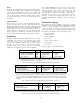
Description Type BACNet Object Modbus Register
Light Switch Inputs GE-1600i RO MI101-116 Fn 4, 01 – 16
Light Switch Inputs (1
st
GE-1600R) RO MI201-216 Fn 4, 17 – 32
Light Switch Inputs (2
nd
GE-1600R) RO MI301-316 Fn 4, 33 – 48
Light Switch Inputs (3
rd
GE-1600R) RO MI401-416 Fn 4, 49 – 64
Light Switch Inputs (4
th
GE-1600R) RO MI501-502 Fn 4, 65 – 66
Light Switch State Text/Configuration MIC1 *
* MIC selected with the LCD Programmer.
Table 6. Local switch inputs and corresponding BACNet object and Modbus register values.
Associated Objects
Analog input configuration (AIC) objects define the scale
range translation used to translate the physical analog-to-
digital (A/D) value to an analog input’s object value (e.g.
0–100%). These objects are listed in Table 7.
Description Type
BACNet
Object
Modbus
Register
Photodiode (RPSEN-IN)
threshold configuration
RO AIC1 *
Photosensor (generic)
threshold configuration
RO AIC2 *
* MIC selected with the LCD Programmer.
Table 7. Analog input configuration objects and corresponding BACNet
object and Modbus register values.
Lighting Groups
The Lighting Group (LG) objects are used to set up the
logical situations for the ROCB outputs. Setup of a
Lighting Group configuration is possible with the LCD
Programmer. These objects are listed in Table 8.
Lighting Outputs
The Binary Output (BO) or Lighting Group (LG) objects
are controlled by the logical situation of the LG. (Note: a
Lighting Group object cannot reference itself.)
Light Switch
The Lighting Group is designed to control many outputs,
but can be set to work with just one, and a light switch
reference allows assigning an object that can transition a
single lighting output reference
ON or OFF. The Lighting
Group and light switch work as “last writers” to the
lighting outputs. So if the LG writes
ON, all the defined
outputs will be
ON regardless of the light switch values.
After the LG write, if the light switch is transitioned
OFF,
then the related output is commanded
OFF and the
remaining outputs stay on.
Group Control
Setup is used for common group control (logical ORing),
as follows.
• Lighting Group – When the referenced Lighting
Group is
ON, the referencing LG is ON. When the
referenced Lighting Group transitions from
ON to
OFF, the referencing LG is relinquished and the logic
native to that Lighting Group resumes control.
(Note: a Lighting Group object cannot reference
itself.)
• Off-time delay – The amount of time after the
referenced Lighting Group (LG) transitions from
ON
to OFF before the referencing Lighting Group is
relinquished.
Override Input
Allows an object to override the Lighting Group (LG) for
the override time. The LG override is triggered when the
override input object transitions from an
OFF or N/A to
ON. When the override timer expires, it relinquishes the
LG and returns to its given logical state.
Schedule Input
Allows Schedule (SCH) object references to control the
Lighting Group (LG) object. The Lights On and Lights
Off checkboxes set the Schedule to trigger the LG On
Only, Off Only, On & Off, or neither Off nor On.
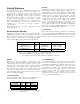
Description Type BACNet Object Modbus Register
Lighting Zones (1–16)
• Output value (ON/OFF)
• Mode (auto/manual)
RW
RW
LG1–16
• PresentValue
• OutOfService
Fn 1/5/15, 301–316*
Fn 1/5/15, 401–416
Setup Properties (see Modbus register map doc)
• Override object reference
• Photocell object reference
• Schedule, Astro ON/OFF times
• Lighting outputs
• Common groups
RO Various
Fn 3/6/16, 3001–9999
• 3005–3008
• 3009–3017
• 3018–3027
• 3028–3155
• 3156–3280
Table 8. Lighting groups and corresponding BACNet object and Modbus register values.