AF-650 GP & AF-600 FPTM High Power Service Manual, Unit Sizes 6x The instructions do not purport to cover all details or variations in equipment nor to provide for every possible contingency to be met in connection with installation, operation or maintenance. Should further information be desired or should particular problems arise which are not covered sufficiently for the purchaser’s purposes, the matter should be referred to the GE company.
High Power Service Manual for Unit Sizes 6x Contents 1 Introduction 5 Purpose 5 AF-6 Product Overview 5 For Your Safety 5 Electrostatic Discharge (ESD) 6 Unit Size Definitions 6 Ratings Tables 6 Optional Components 9 Optional Unit Size 6x components 9 Tools Required 9 General Torque Tightening Values 9 Exploded Views 2 Operator Interface and Control 10 15 Introduction 15 Operating the Frequency Converter 15 Operation and Programming Through the Keypad 15 Keypad 15 Display A
High Power Service Manual for Unit Sizes 6x Intermediate Section 37 Inverter Section 39 Brake Option 41 Cooling Fans 43 Fan Speed Control 43 Load Sharing 44 Specific Card Connections 44 4 Troubleshooting Troubleshooting Tips 45 Exterior Fault Troubleshooting 45 Fault Symptom Troubleshooting 45 Visual Inspection 46 Fault Symptoms 47 No Display 47 Intermittent Display 47 Motor Will not Run 48 Incorrect Motor Operation 49 Warning/Alarm List 54 After Repair Tests 60 5 Frequen
High Power Service Manual for Unit Sizes 6x Signal Test Board 72 Static Test Procedures 73 Rectifier Module Static Test 74 Inverter Module Static Tests 77 Brake IGBT Test 79 Fan Continuity Test 80 Dynamic Test Procedures 82 Split Bus Mode 82 Warnings 83 No Display Text 83 Input Voltage Test 83 Basic Control Card Voltage Test 84 DC Undervoltage Test 84 Input Imbalance of Supply Voltage Test 85 Input Waveform Test 86 Gate Signal Test 88 IGBT Switching Test 89 Current Sensor T
High Power Service Manual for Unit Sizes 6x DC Link Inductor 106 MDCIC Board 108 8 Disassembly/Assembly - Inverter Module For Your Safety 111 GE Training Required 111 Inverter Module 111 Inverter Module, Exploded View 111 Internal Access 112 Power Card 112 Upper Capacitor Bank Assembly (without removing power card) 112 Lower Capacitor Bank Assembly 113 High Frequency Board 114 Gate Drive Card 115 Current Sensor 116 Brake IGBT Module (Optional) 117 IGBT Module 118 9 Disassembly/
High Power Service Manual for Unit Sizes 6x 1 Introduction 1 1.1 Purpose The purpose of this manual is to provide detailed technical information and instructions to enable a qualified technician to identify faults and perform repairs on frequency converters in the unit size 6x range. It provides the reader with a general view of the unit's main assemblies and a description of the internal processing.
High Power Service Manual for Unit Sizes 6x 1. 1 2. Disconnect mains prior to inspection or making repairs. DO NOT touch electrical parts of frequency converter when connected to mains. After removing power from mains, wait 40 minutes before touching any electrical parts. See the label on the front of the frequency converter door for specific discharge time. 3. The STOP key on the keypad does not disconnect mains. 4.
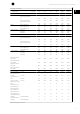
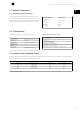
High Power Service Manual for Unit Sizes 6x Mains supply 3 x 380-480 V AF-600 FP 650 750 900 1000 1200 1350 AF-650 GP 600 650 750 900 1000 1200 880 990 1120 1260 1460 1720 V) 968 1089 1232 1386 1606 1892 Nominal [A] (441-500 V) 780 890 1050 1160 1380 1530 Model number 1 Light duty (LD) current ratings (110 %): Output current Nominal [A] (380-440 V) MAX (60 sec) [A] (380-440 MAX (60 sec) [A] (441-500 Output Typical shaft output V) 858 979 1155 1276 1518 1683 Nom
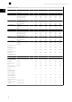
High Power Service Manual for Unit Sizes 6x Mains supply 3 x 525 - 690 V 1 Model number AF-600 FP 750 950 1050 1150 1350 1550 AF-650 GP 900 1000 1150 1250 1350 1550 Light duty (LD) current ratings (110 %): Output current Output Typical shaft output Nominal [A] (525-550 V) 763 889 988 1108 1317 1479 MAX (60 sec) [A] (525-550 V) 839 978 1087 1219 1449 1627 Nominal [A] (551-690 V) 730 850 945 1060 1260 1415 MAX (60 sec) [A] (551-690 V) 803 935 1040 1166 1386 1557
High Power Service Manual for Unit Sizes 6x 1.7 Optional Components 1 1.7.1 Optional Unit Size 6x components Units are manufactured in different configurations due to the optional components available. Depending on the unit configuration, optional equipment may be mounted in the inverter, rectifier or option cabinet. The table below lists the components available and the cabinet where it is factory installed.
High Power Service Manual for Unit Sizes 6x 1 1.10 Exploded Views 1 2 3 4 16 5 6 7 8 14 9 13 12 10 11 Inverter cabinet exploded view (cabinet with 2 inverter modules shown). Units with 3 inverter modules are similar.
High Power Service Manual for Unit Sizes 6x 1 1 2 3 4 5 6 12 7 11 10 8 9 Illustration 1.
High Power Service Manual for Unit Sizes 6x 1 1 2 3 12 4 11 5 10 6 9 8 7 Rectifier cabinet exploded view 1 2 3 4 5 6 12 Rectifier module DC bus bar SMPS fuse (Optional) back AC fuse mounting bracket (T) (Optional) middle AC fuse mounting bracket (S) (Optional) front AC fuse mounting bracket (R) 7 8 9 10 11 12 Module lifting eye bolts (mounted on vertical strut) Module heatsink fan Fan door cover SMPS fuse Power card Panel connectors
High Power Service Manual for Unit Sizes 6x 130BX335.
1 1 5 4 2 3 Option cabinet exploded view 1 2 3 14 Contactor RFI filter Mains AC power input terminals 4 5 Circuit breaker or disconnect AC mains/line fuses 130BX334.
High Power Service Manual for Unit Sizes 6x 2 Operator Interface and Control 2.1 Introduction Frequency converters are designed with self-diagnostic circuitry to isolate fault conditions and activate display messages which greatly simplify troubleshooting 2 and service. The operating status of the frequency converter is displayed in real-time. Virtually every command given to the frequency converter results in some indication on the Keypad display.
High Power Service Manual for Unit Sizes 6x 2.2.3 Display Area a. The top line shows controller status when in status mode or two variables selected in par. K-10 Active Set-up, such as direction of rotation or active setup 2 b. The motor values displayed are selected by parameter choices in par. K-20 Display Line 1.1 Small, par. K-21 Display Line 1.2 Small, par. K-22 Display Line 1.3 Small, par. K-23 Display Line 2 Large, and par. K-24 Display Line 3 Large. Each value has dimension scaling.
High Power Service Manual for Unit Sizes 6x 2.2.5 Navigation Keys Navigation keys are used for programming functions, moving the display cursor, and speed control in local controller operation. Controller status indicator lights are also located in this area. 2 Back Reverts to the previous step or list in the navigation structure. Cancel The last change or command will be cancelled, as long as the display mode has not changed.
High Power Service Manual for Unit Sizes 6x The following control signals will still be available when [Hand] is activated: [Hand] - [Off] - [Auto] - [Reset] keys Coasting stop inverse (motor coasting to stop) 2 Reversing Set-up select Stop command from serial communication Quick stop DC brake Off Stops the connected motor. The key can be Enabled [1] or Disabled [0] in par. K-41 [Off] Button on Keypad.
High Power Service Manual for Unit Sizes 6x 2.2.8 Restore Factory Settings There are two ways to restore the drive to factory settings: Recommended restore and manual restore. Please be aware that they have different impact according to the below description. Recommended restore (via par. H-03 Restore Factory Settings) 2 Par. H-03 Restore Factory Settings restores all except: 1. Select par. H-03 Restore Factory Settings 2. Press [OK] Par. O-30 Protocol 3. Select [2] Restore Factory Settings Par.
High Power Service Manual for Unit Sizes 6x 2.3 Status Messages Status messages appear in the bottom of the display - see the example below. 2 The left part of the status line indicates the active operation mode of the frequency converter. The centre part of the status line indicates the references site. The last part of the status line gives the operation status, e.g. Running, Stop or Stand by. Other status messages may appear related to the software version and frequency converter type.
High Power Service Manual for Unit Sizes 6x Bus Jog 2 PROFIDrive profile was selected in par. O-10 Control Word Profile. The Jog 2 function is activated via serial communication. The motor is running with par. O-91 Bus Jog 2 Speed. Catch up The output frequency is corrected by the value set in par. F-62 Catch up/slow Down Value. 1. Catch up is selected as a function for a digital input (parameter group E-##). The corresponding terminal is active. 2. Catch up was activated via serial communication.
High Power Service Manual for Unit Sizes 6x Jogging The motor is running with par. C-21 Jog Speed [RPM]. 2 1. Jog was selected as function for a digital input (parameter group E-##). The corresponding terminal (e.g. Terminal 29) is active. 2. The Jog function is activated via the serial communication. 3. The Jog function was selected as a reaction for a monitoring function (e.g. No signal). The monitoring function is active. Kinetic backup In par.
High Power Service Manual for Unit Sizes 6x Sleep Boost (AF-600 FP only) The boost function in par. AP-45 Setpoint Boost is enabled. This function is only possible in Closed loop operation. Sleep Mode (AF-600 FP only) The sleep mode function is enabled by means of either No Flow Detection or Minimum Speed Detection or via an external signal applied to one of the digital input (parameter group E-##). This means that at present the motor has stopped, but that it will restart automatically when required.
High Power Service Manual for Unit Sizes 6x 2.4 Service Functions Service information for the frequency converter can be shown on display lines 2 3 and 4. Included in the data are counters that tabulate operating hours, power ups and trips; fault logs that store frequency converter status values present at the 20 most recent events that stopped the frequency converter; and frequency converter nameplate data.
High Power Service Manual for Unit Sizes 6x 2.5 Frequency Converter Inputs and Outputs The frequency converter operates by receiving control input signals. The frequency converter can also output status data or control auxiliary devices. Control input is connected to the frequency converter in three possible ways. One way for frequency converter control is through the Keypad on the front of the frequency converter when operating in local (hand) mode.
High Power Service Manual for Unit Sizes 6x 2.5.1 Input signals The frequency converter can receive two types of remote input signals: digital or analog. Digital inputs are wired to terminals 18, 19, 20 (common), 27, 29, 32, and 33. Analog or digital inputs are wired to terminals 53 or 54 and 55 (common). The terminal functions are set by a switch found by removing the Keypad. Some 2 options may include additional terminals.
High Power Service Manual for Unit Sizes 6x 2.6 Control Terminals Control terminals must be programmed. Each terminal has specific functions it is capable of performing and a numbered parameter associated with it. See table Control Terminals and Associated Parameters. The setting selected in the parameter enables the function of the terminal. 2 It is important to confirm that the control terminal is programmed for the correct function.
High Power Service Manual for Unit Sizes 6x 2.7 Control Terminal Functions The following describes the functions of the control terminals. Many of these terminals have multiple functions determined by parameter settings. Some options 2 provide additional terminals. See illustration below. Terminal No. Function 01, 02, 03 and 04, 05, 06 Two Form C output relays. Maximum 240 VAC, 2 A. Minimum 24 VDC, 10 mA or 24 VAC, 100 mA. Can be used for indicating status and warnings.
High Power Service Manual for Unit Sizes 6x 2.8 Earthing Screened Cables It is recommended that screened control cables be connected with cable clamps at both ends to the metal cabinet of the frequency converter. The table below shows earth cabling for optimal results. 2 Correct earthing Control cables and cables for serial communication must be fitted with cable clamps at both ends to ensure the best possible electrical connection.
High Power Service Manual for Unit Sizes 6x 3 30
High Power Service Manual for Unit Sizes 6x 3 Internal Frequency Converter Operation 3.1 General This section is intended to provide an operational overview of the frequency converter’s main assemblies and circuitry. With this information, a repair technician should have a better understanding of the frequency converter's operation and aid in the troubleshooting process. 3.
High Power Service Manual for Unit Sizes 6x 3.2.1 Logic Section The control card contains most of the logic section (see Illustration below). The primary logic element of the control card is a microprocessor, which supervises and controls all functions of frequency converter operation. In addition, separate PROMs contain the parameters to provide the user with programmable options. These parameters are programmed to enable the frequency converter to meet specific application requirements.
High Power Service Manual for Unit Sizes 6x Two relays for monitoring the status of the frequency converter are located on the power card. These are programmable through parameter group E-##. The relays are Form C, meaning it has one normally open contact and one normally closed contact on a single throw. The contacts of the relay are rated for a maximum load of 240 VAC at 2 Amps resistance.
High Power Service Manual for Unit Sizes 6x 3.2.3 Power Section The high voltage power section consists of AC input terminals, AC and DC bus bars, fusing, harnessing, AC output, and optional components. The power section (see illustration below) also contains circuitry for the soft charge and SCR/diode modules in the rectifier; the DC bus filter circuitry containing the DC coils, often referred to as the intermediate or DC bus circuit; and the output IGBT modules which make up the inverter section.
High Power Service Manual for Unit Sizes 6x 3.3 Sequence of Operation 3.3.1 Rectifier and Option Cabinet When input power is first applied to the frequency converter, it enters through the input terminals (L1, L2, L3) and on to the disconnect or/and RFI option, depending on the unit's configuration (see illustration 3-4). If equipped with optional fuses, these fuses (FU1, FU2, FU3) limit damage caused by a short circuit in the power section.
92 93 S L2 T L3 SW1 FK3 3 FK2 FU2 FU3 2 1 - + - CBL15 RFI CARD MK1 Illustration 3.
High Power Service Manual for Unit Sizes 6x 3.3.2 Intermediate Section Following the rectifier section, voltage passes to the intermediate section. (See following illustration). This rectified voltage is smoothed by an LC filter circuit consisting of the DC bus inductor and the DC bus capacitor banks per each inverter module. The DC bus inductor provides series impedance to changing current.
Illustration 3.
High Power Service Manual for Unit Sizes 6x 3.3.3 Inverter Section In the inverter section, gate signals are received from the control card (through the MDCIC), and sent to each inverter module's power card and the gate drive card to the IGBT gates. (See illustration titledIntermediate and Inverter Sections).The output of each IGBT, connected in series, first passes through the current sensors.
High Power Service Manual for Unit Sizes 6x Illustration 3.
High Power Service Manual for Unit Sizes 6x 3.3.4 Brake Option For frequency converters equipped with the dynamic brake option, two brake IGBTs along with terminals 81(R-) and 82(R+) are included in each inverter module for connecting an external brake resistor(s). The function of the brake IGBT (see Illustration Brake Option) is to limit the voltage in the intermediate circuit, whenever the maximum voltage limit is exceeded.
High Power Service Manual for Unit Sizes 6x Illustration 3.
High Power Service Manual for Unit Sizes 6x 3.3.5 Cooling Fans All frequency converters in this size range are equipped with cooling fans to provide airflow along the heatsinks and within the enclosures. All fans are powered by mains voltage which is stepped down by autotransformers and regulated to 200 or 230 VAC by circuitry provided on the power cards. On/off and high/low speed control of the fans is provided to reduce overall acoustical noise and extend the life of the fans.
High Power Service Manual for Unit Sizes 6x 3.3.7 Load Sharing Units with the built-in load sharing option contain terminals 89 (+) DC and 88 (-) DC. Within the frequency converter, these terminals connect to the DC bus in front of the DC link reactor and bus capacitors. The use of the load sharing terminals can take on two different configurations. 3 In one method, the terminals are used to tie the DC bus circuits of multiple frequency converters together.
High Power Service Manual for Unit Sizes 6x 4 Troubleshooting 4.1 Troubleshooting Tips Before attempting to repair a frequency converter, here are some tips to follow to make the job easier and possibly prevent unnecessary damage to functional components. 1. Ensure that no voltage is present on the frequency converter prior to troubleshooting. Check for the presence of AC input voltage and DC bus voltage and ensure there is none before working on the unit.
High Power Service Manual for Unit Sizes 6x 4.4 Visual Inspection The table below lists a variety of conditions that require visual inspection as part of any initial troubleshooting procedure. Inspect For Auxiliary equipment Cable routing 4 Control wiring Drive cooling Drive display Drive interior EMC considerations Environmental conditions Earthing Input power wiring Motor Output to motor wiring Programming Proper clearance Vibration Table 4.
High Power Service Manual for Unit Sizes 6x 4.5 Fault Symptoms 4.5.1 No Display To troubleshoot no display: Check that power is supplied. Cycle power to the unit. Restore the drive. (See section Tips and Tricks.) 4.5.2 Intermittent Display 4 Cutting out or flashing of the entire display and power LED indicates that the power supply (SMPS) is shutting down as a result of being overloaded. This may be due to improper control wiring or a fault within the frequency converter itself.
High Power Service Manual for Unit Sizes 6x 4.5.3 Motor Will not Run In the event that this symptom is detected, first verify that the unit is properly powered up (display is lit) and that there are no warning or alarm messages displayed. The most common cause of this is either incorrect control logic or an incorrectly programmed frequency converter. Such occurrences will result in one or more of the following status messages being displayed. Keypad Stop The [Off] key has been pressed.
High Power Service Manual for Unit Sizes 6x 4.5.4 Incorrect Motor Operation Occasionally, a fault can occur where the motor will continue to run, but not in the correct manner. The symptoms and causes may vary considerably. Many of the possible problems are listed below by symptom along with recommended procedures for determining their causes. Wrong speed/unit will not respond to command Possible incorrect reference (speed command).
High Power Service Manual for Unit Sizes 6x 4.6 Alarms and Warnings A warning or an alarm is signalled by the relevant LED on the front of the frequency converter and indicated by a code on the display. A warning remains active until its cause is no longer present. Under certain circumstances operation of the motor may still be continued. Warning messages may be critical, but are not necessarily so. In the event of an alarm, the frequency converter will have tripped.
High Power Service Manual for Unit Sizes 6x No.
High Power Service Manual for Unit Sizes 6x 4 No.
High Power Service Manual for Unit Sizes 6x Alarm Word and Extended Status Word Bit Hex Dec Alarm Word Warning Word 0 00000001 1 Brake Check Brake Check Extended Status Word Ramping 1 00000002 2 Pwr. Card Temp Pwr. Card Temp Auto Tune Running 2 00000004 4 Earth Fault Earth Fault Start CW/CCW 3 00000008 8 Ctrl.Card Temp Ctrl.Card Temp Slow Down 4 00000010 16 Ctrl. Word TO Ctrl.
High Power Service Manual for Unit Sizes 6x 4.6.1 Warning/Alarm List WARNING 1, 10 Volts low: The 10 V voltage from terminal 50 on the control card is below 10 V. Alarm/warning limits: Voltage ranges 3 x 380 - 480/500 V 3 x 525 - 690 V [VDC] 373 410 810/840 [VDC] 553 585 1099/1109 855 1130 Remove some of the load from terminal 50, as the 10 V supply is overloaded. Max. 15 mA or minimum 590 ohm. Troubleshooting: Remove the wiring from terminal 50.
High Power Service Manual for Unit Sizes 6x WARNING/ALARM 10, Motor Electronic Thermal Overload over tempera- ALARM 14, Earth fault: ture: There is a discharge from the output phases to earth, either in the cable be- According to the electronic thermal protection (Electronic Thermal Overload), tween the frequency converter and the motor or in the motor itself. the motor is too hot. It can be chosen if the frequency converter is to give a Turn off the frequency converter and remove the earth fault.
High Power Service Manual for Unit Sizes 6x WARNING 23, Internal fan fault ALARM 29, Heatsink temp: The fan warning function is an extra protective function that checks if the fan The maximum temperature of the heatsink has been exceeded. The temper- is running/mounted. The fan warning can be disabled in par. SP-53 Fan Mon- ature fault will not be reset until the temperature falls below a defined heat- itor ([0] Disabled). sink temperature.
High Power Service Manual for Unit Sizes 6x ALARM 38, Internal fault: Contact the local GE supplier. 0 256-258 Serial port cannot be restored.
High Power Service Manual for Unit Sizes 6x ALARM 54, Auto Tune motor too small: ALARM 68, Safe Stop Activated: The motor is too small for the Auto Tune to be carried out. Safe Stop has been activated. To resume normal operation, apply 24 V DC to ALARM 55, Auto Tune parameter out of range: terminal 37, then send a reset signal (via Bus, Digital I/O, or by pressing [RE- The parameter values found from the motor are outside acceptable range.
High Power Service Manual for Unit Sizes 6x ALARM 93, Dry pump: ALARM 246, Power card supply A no-flow situation and high speed indicate that the pump has run dry. See This alarm is only for unit size 6x frequency converters. It is equivalent to Alarm parameter group AP-2#. 46. The report value in the alarm log indicates which power module generated ALARM 94, End of curve: the alarm: Feedback stays lower than the setpoint which may indicate leakage in the 1 = left most inverter module.
High Power Service Manual for Unit Sizes 6x 4.7 After Repair Tests Following any repair to a frequency converter or testing of a frequency converter suspected of being faulty, the following procedure must be followed to ensure that all circuitry in the frequency converter is functioning properly before putting the unit into operation. 4 1. Perform visual inspection procedures as described in the table Visual Inspection. 2. Perform static test on the drive as described in Static Test Procedures. 3.
High Power Service Manual for Unit Sizes 6x 5 Frequency Converter and Motor Applications 5.1 Torque Limit, Current Limit, and Unstable Motor Operation Excessive loading of the frequency converter may result in warning or tripping on torque limit, overcurrent, or inverter time. This is not a concern if the frequency converter is properly sized for the application and intermittent load conditions cause anticipated operation in torque limit or an occasional trip.
High Power Service Manual for Unit Sizes 6x 5.1.1 Overvoltage Trips This trip occurs when the DC bus voltage reaches its DC bus alarm voltage high (see ratings tables in introductory section). Prior to the trip, the frequency converter will display a high voltage warning. Most times an over voltage condition is due to fast deceleration ramps with respect to the inertia of the load. During deceleration of the load, inertia of the system acts to sustain the running speed.
High Power Service Manual for Unit Sizes 6x 5.1.3 Control Logic Problems Problems with control logic can often be difficult to diagnose, since there is usually no associated fault indication. The typical complaint is simply that the frequency converter does not respond to a given command. There are two basic commands that must be given to any frequency converter in order to obtain an output. First, the frequency converter must be told to run (start command).
High Power Service Manual for Unit Sizes 6x Quite often, the indications of motor problems are similar to those of a defect in the frequency converter itself. To determine whether the problem is internal or external to the frequency converter, disconnect the motor from the frequency converter output terminals. If the three voltage measurements are balanced, the frequency converter is functioning correctly. The problem therefore is external to the frequency converter.
High Power Service Manual for Unit Sizes 6x 5.2.3 Current Sensor Faults When a current sensor fails, it is indicated sometimes by an overcurrent alarm that cannot be reset, even with the motor leads disconnected. Most often, however, the frequency converter will experience frequent false earth fault trips. This is due to the DC offset failure mode of the sensors. To explain this it is necessary to investigate the internal makeup of a Hall effect type current sensor.
High Power Service Manual for Unit Sizes 6x 5.3.2 Sources of EMI Modern frequency converters (see illustration below) utilise Insulated-Gate Bipolar Transistors (IGBTs) to provide an efficient and cost effective means to create the Pulse Width Modulated (PWM) output waveform necessary for accurate motor control. These devices rapidly switch the fixed DC bus voltage creating a variable frequency, variable voltage PWM waveform.
High Power Service Manual for Unit Sizes 6x 5.3.3 EMI Propagation Drive AC Line 130BX138.11 Frequency converter generated EMI is both conducted to the mains and radiated to nearby conductors. See illustrations below. Motor Motor cable Stray capacitance Stray capacitance 5 Ground Potential 1 Potential 2 Potential 3 Illustration 5.2: Earth Currents Stray capacitance between the motor conductors, equipment earth, and other nearby conductors results in induced high frequency currents.
Drive AC Line Motor Motor cable 130BX140.12 High Power Service Manual for Unit Sizes 6x Stray capacitance AC Line Illustration 5.4: Alternate Signal Conductor Currents 5 High frequency currents can be coupled into the mains supplying the frequency converter when the mains conductors are located close to the motor cables.
High Power Service Manual for Unit Sizes 6x 5.3.4 Preventive Measures EMI related problems are more effectively alleviated during the design and installation phases rather than after the system is in service. Many of the steps listed here can be implemented at a relatively low cost when compared to the cost for identifying and fixing the problem later in the field. Earthing The frequency converter and motor should be solidly earthed to the equipment frame.
High Power Service Manual for Unit Sizes 6x 5.3.5 Proper EMC Installation Shown in the illustration below is a correct installation with EMC considerations in mind. Although most installations will not follow all the recommended practices the closer an installation resembles this example the better immunity the network will have against EMI. Should EMI problems arise in an installation, refer to this example.
High Power Service Manual for Unit Sizes 6x 6 Test Procedures 6.1 Introduction Touching electrical parts of frequency converter may be fatal even after equipment has been disconnected from AC power. Wait 40 minutes after power has been removed before touching any internal components to ensure that capacitors have fully discharged. This section contains detailed procedures for testing unit size 6x series frequency converters.
High Power Service Manual for Unit Sizes 6x 6.1.2 Signal Test Board The signal test board can be used to test circuitry within the frequency converter and provides easy access to test points. The test board plugs into the top of the 130BX66.10 modules. Its use is described in the procedures where called out. See Section 9, Signal Test Board, for detailed pin descriptions. 6 Illustration 6.
High Power Service Manual for Unit Sizes 6x 6.2 Static Test Procedures All static tests should be made with a meter capable of testing diodes. Use a digital volt/ohm meter (VOM) set on the diode scale or an analog ohmmeter set on Rx100 scale. Before making any checks disconnect all input, motor and brake resistor connections. NB! Perform the static test procedures described in this section in the order presented for best troubleshooting results.
High Power Service Manual for Unit Sizes 6x 6.2.
High Power Service Manual for Unit Sizes 6x 6.2.1.1 Soft Charge Fuse Test This test is used to determine if any of the soft charge fuses are open. Use the 12-pin connector on the top of the rectifier module for testing. 1. L1 to pins 6, 11, and 12 (red wires). 2. L2 to pins 4, 9, and 10 (white wires). 3. L3 to pins 2, 7, and 8 (black wires). A measurement of 0 Ω indicates good continuity. Replace any open fuses (infinite resistance). Note that the rectifier module must be removed to replace fuses.
High Power Service Manual for Unit Sizes 6x Main rectifier circuit test part I 1. Connect positive (+) meter lead to positive (+) DC bus. 2. Connect negative (–) meter lead to terminals L1, L2, and L3 in turn. Each reading should show infinity. The meter will start at a low value and slowly climb towards infinity due to capacitance within the drive being charged by the meter.
High Power Service Manual for Unit Sizes 6x 6.2.2 Inverter Module Static Tests The inverter module is primarily made up of the IGBTs used for switching the DC bus voltage to create the output to the motor. The IGBTs are grouped into three per module. The frequency converter also has snubber capacitors on each IGBT module. Before testing the inverter module, ohm check the top and bottom of the DC fuses to ensure no voltage is present.
High Power Service Manual for Unit Sizes 6x 6.2.2.2 Inverter test part I 1. Connect the positive (+) meter lead to the (+) positive DC bus bar. 2. Connect the negative (–) meter lead to terminals U, V, and W in sequence. 1 2 3 4 6 5 1 2 3 Top (-)DC link fuse bus bar (-)DC link fuse Top (+)DC link fuse bus bar 4 5 (+)DC link fuse Bottom (+)DC link fuse bus bar Each reading should show infinity.
High Power Service Manual for Unit Sizes 6x 6.2.3 Brake IGBT Test This test can only be carried out on units equipped with a dynamic brake option. 1. 2. Remove the safety covers to access the unit. Note the position of the brake jumper bus bars prior to removal. The tops of the bus bars are connected to the motor lead bus bars as referred to in the following test procedures. 3. Remove the brake jumper bus bars Brake IGBT test part I 1.
High Power Service Manual for Unit Sizes 6x 6.2.4 Fan Continuity Test Make all continuity checks using an ohmmeter set to Rx1 scale. A digital or analog ohmmeter can be used. Some instability may result when measuring resistance of a transformer with a multimeter. This can be reduced by turning off the auto-ranging function and setting the measurement manually.
High Power Service Manual for Unit Sizes 6x Check 4: Inverter Cabinet and Rectifier Cabinet Door Fans This checks the wiring between the Inverter Module and the Cabinet Door Fans. All three door fans are controlled from Inverter Module number 2 (middle inverter module in 62/64 drive or right inverter module in 61/63 drive). 1. Unplug the 10-pin connector from the top of Inverter Module number 2. Read the terminals on the wire harness side of the connector (male connector). 2.
High Power Service Manual for Unit Sizes 6x Incorrect reading An incorrect reading indicates a failed fan. Replace the fan. If the fan is OK, the problem is the wire harness inside the module. Remove the module in question and replace the fan wire harness. Check 7: Option Cabinet Door Fan (only 63/64) This checks the wiring between the Rectifier Module and the Option Cabinet Door Fan. 1. Unplug the 8-pin connector from the top of the Rectifier Module.
High Power Service Manual for Unit Sizes 6x 6.3.2 Warnings Never disconnect the input cabling to the frequency converter with power applied due to danger of severe injury or death. Take all the necessary safety precautions for system start up prior to applying power to the frequency converter. For dynamic test procedures, main input power is required and all devices and power supplies connected to mains are energized at rated voltage.
High Power Service Manual for Unit Sizes 6x Incorrect reading An incorrect reading here requires that the main supply be investigated further. Typical items to check would be: Open (blown) input fuses or tripped circuit breakers Open disconnects or line side contactors Problems with the power distribution system Open (blown) input fuses or tripped circuit breakers usually indicate a more serious problem. Prior to replacing fuses or resetting breakers, perform static tests.
High Power Service Manual for Unit Sizes 6x 6.3.7 Input Imbalance of Supply Voltage Test Theoretically, the current drawn on all three input phases should be equal. Some imbalance may be seen, however, due to variations in the phase to phase input voltage and, to some degree, single phase loads within the frequency converter itself. A current measurement of each phase will reveal the balanced condition of the line.
High Power Service Manual for Unit Sizes 6x 6.3.8 Input Waveform Test Testing the current waveform on the input of the frequency converter can assist in troubleshooting mains phase loss conditions or suspected problems with the SCR/diode modules. Phase loss caused by the mains supply can be easily detected. In addition, the rectifier section is controlled by SCR/diode modules.
High Power Service Manual for Unit Sizes 6x With a phase loss, the current waveform of the remaining phases would take on the appearance shown below. 6 Illustration 6.5: Input Current Waveform with Phase Loss. Always verify the condition of the input voltage waveform before forming a conclusion. The current waveform will follow the voltage waveform. If the voltage waveform is incorrect proceed to investigate the reason for the AC supply problem.
High Power Service Manual for Unit Sizes 6x 6.3.9 Gate Signal Test 1. Remove the output bus bars from all inverter modules. 2. Power drive in split bus mode. (See split bus powering). 3. Connect a 24VDC power supply to the (+) and (-) DC bus bars. 4. Connect the signal test board (p/n 6KAF6H8437) to the 30 pin connector at the top of the inverter module. 5. Apply a run command and a speed command above 0 RPM. (Hand Start mode is sufficient). 6.
High Power Service Manual for Unit Sizes 6x 6.3.10 IGBT Switching Test Power the unit in the split bus mode as described in the gate signal test procedure. 2. Observe the phase-to- phase output waveforms on all three phases with the oscilloscope. 3. All waveform readings should appear similar to the below figure. 4. Repeat this procedure for all inverter modules. 130BX337.10 1. 6 Illustration 6.6: Output waveform graphic Incorrect reading Indicates that an IGBT or gate driver card is defective.
High Power Service Manual for Unit Sizes 6x Incorrect reading If an incorrect reading was obtained from the above tests, further tests of the current feedback signals are required using the signal test board. See Testing Current Feedback with the Signal Test Board. 6.3.12 Testing Current Feedback with the Signal Test Board If the control card parameters are setup to provide holding torque while at zero speed, the current displayed will be greater than expected. To make this test, disable such parameters.
High Power Service Manual for Unit Sizes 6x 6.3.13 Input Terminal Signal Test The presence of signals on either the digital or analog input terminals of the drive can be verified on the drive display. Digital or analog input status can be selected in the display using the [DISPLAY MODE] key and the [+] and [-] keys on the keypad. Digital inputs With digital inputs displayed, control terminals 18, 19, 27, 29, 32, 33 are shown left to right, with a 1 indicating the presence of a signal.
High Power Service Manual for Unit Sizes 6x Verify the reference voltage power supply is correct as follows. 1. With a voltmeter measure voltage at control card terminal 50 with respect to terminal 55. Meter should read between 9.2 and 11.2 VDC. If the 10 V supply voltage is not present, conduct the Control Card Voltage Test earlier in this section. If the 10 volts is present proceed with checking the individual inputs as follows. 2. Connect (-) negative meter lead to reference terminal 55. 3.
High Power Service Manual for Unit Sizes 6x 6.4 Module-level Static Test Procedures 6.4.1 Inverter Module Heatsink Temperature Sensor Test Remove the inverter module from the drive in accordance with disassembly procedures. The temperature sensor is an NTC (negative temperature coefficient) device. As a result, high resistance means low temperature. As temperature decreases, resistance increases. Each IGBT module has a temperature sensor mounted internally.
High Power Service Manual for Unit Sizes 6x 4. Connect the positive (+) meter lead to the negative (-) MK3 (C). Connect the negative (-) meter lead to MK1 terminals R, S, and T in sequence. Each reading should show a diode drop. 5. Reverse the meter leads with the negative (-) meter lead to the negative (-) MK3 (C). Connect the positive (+) meter lead to MK1 terminals R, S, and T in sequence. Each reading should show open.
High Power Service Manual for Unit Sizes 6x 6.5 After Repair Drive Test 6.5.1 Procedure Following any repair to a frequency converter or testing of a frequency converter suspected of being faulty, the following procedure must be followed to ensure that all circuitry in the frequency converter is functioning properly before putting the unit into operation. 1. Perform visual inspection procedures as described in the table Visual Inspection. 2.
High Power Service Manual for Unit Sizes 6x 7 96
High Power Service Manual for Unit Sizes 6x 7 Top Level Module Removal Instructions 7.1 Before Proceeding 7.1.1 High Voltage Warning Frequency converters contain dangerous voltages when connected to mains voltage. No disassembly should be attempted with power applied. Remove power to the frequency converter and wait at least 40 minutes to let the frequency converter capacitors fully discharge. Only a competent technician should carry out service.
High Power Service Manual for Unit Sizes 6x 7.1.4 Tools Required Operating Instructions for the Drives Series Frequency Converter Metric socket set Socket extensions Torx driver set Torque wrench Needle nose pliers Magnetic sockets Ratchet Hex wrench set Screwdrivers 7–19 mm 100 mm–150 mm (4 in and 6 in) T10 - T50 0.
High Power Service Manual for Unit Sizes 6x 7.2 Instructions 7.2.1 AC Line Input Fuses AC Fuse Location AC line fuses are optional. AC fuses are located in the rectifier cabinet if they are the only power option added to the frequency converter. If additional power options are present, the AC fuses will be located in the options cabinet. AC Fuses Located in the Rectifier Cabinet 1. Remove bottom safety cover from rectifier cabinet. Note: Fuses must be removed sequentially, front to back.
High Power Service Manual for Unit Sizes 6x 7.2.2 DC Link Fuses There are two DC link fuses for each inverter located on top of the inverter. 1. Remove covers from inverter cabinet to gain access. 2. Remove bus bars securing top of fuses by removing attaching bolts (8mm). 3. Remove bolts securing bottom of fuses (8mm).
High Power Service Manual for Unit Sizes 6x 7.2.3 Door Fans 1. Disconnect the leads from the terminal strip on the fan, noting the correct terminal that each wire is connected to for reassembly. 2. Remove the four (8mm) mounting nuts from each corner of the fan assembly. 3. Remove fan assembly from mounting/filter housing assembly in door. 4. Reassemble in reverse order. Note that Unit size 6x drives are designed for fan airflow into the cabinets.
High Power Service Manual for Unit Sizes 6x 7.2.5 Rectifier Module 1. Remove center mounted safety cover from rectifier module by removing screws (8mm). 2. Remove top mounted safety cover from rectifier module by removing screws (8mm). 3. Remove two DC bus bars from top of rectifier by removing four nuts (8mm) securing each bus bar (two on each end of bus bar). 4. Remove three AC input power bus bars in order to free module for removal. Bus bars are stacked one behind the other.
High Power Service Manual for Unit Sizes 6x 7.2.6 Inverter Module 1. Remove safety covers from front of inverter module by removing attaching screws. 2. If present, remove two (optional) brake bus bars by removing four screws (M8), one on each end of both bus bars. 3. Remove three output motor bus bars by removing six screws (M8), one on each end of each bus bars. 4. Disconnect ribbon cable from top of inverter module. 5.
High Power Service Manual for Unit Sizes 6x 7.2.7 MDCIC Mounting Panel 1. Remove top mounted safety cover from inverter module by removing attaching screws (8mm). 2. Disconnect ribbon cable from control card. 3. Before removing MDCIC ribbon cable from each inverter module, note which cable connects to each module for reassembly. Remove MDCIC ribbon cable from each inverter module. 4.
High Power Service Manual for Unit Sizes 6x 7.2.8 Fan Transformers 1. Remove MDCIC panel in accordance with instructions. 2. Disconnect electrical connector from fan transformer. 3. Remove nut (M8) from center of fan transformer securing transformer to panel. Reinstall fan transformer in reverse order of this procedure. 1 2 3 7 130BX255.
High Power Service Manual for Unit Sizes 6x 7.2.9 DC Link Inductor 1. Remove MDCIC panel in accordance with instructions. (Fan transformers do not need to be removed.) 2. Remove 2 bus bars covering inductor by removing four screws (8mm) on each bus bar. 3. Remove 4 mounting bracket bus bars that bus bars removed previously in Step 2 were mounted to by removing screw (8mm) from each mounting bracket. 4.
High Power Service Manual for Unit Sizes 6x 2 1 3 2 3 2 130BX254.
High Power Service Manual for Unit Sizes 6x 7.2.10 MDCIC Board 1. Remove two screws from left side of MDCIC cover. 2. Disconnect ribbon cable from left side of MDCIC board by gently pulling connector to left (as opposed to pulling connector out toward you). 3. Swing cover door open to access MDCIC board. Cover can be removed. 4. Note position of ribbon cables before removing for reinstallation. Remove ribbon cables. 5.
High Power Service Manual for Unit Sizes 6x 7 130BX267.
High Power Service Manual for Unit Sizes 6x 8 110
High Power Service Manual for Unit Sizes 6x 8 Disassembly/Assembly - Inverter Module 8.1 For Your Safety 8.1.1 GE Training Required Only GE trained and certified technicians are permitted to test and repair components within the unit modules. The procedures described in this section are intended for GE qualified technicians. Repair work conducted by non-certified technicians can result in personal injury or equipment damage. 8.2 Inverter Module 8.2.
High Power Service Manual for Unit Sizes 6x 8.2.2 Internal Access 1. 2. Remove inverter module from frequency converter in accordance with instruction in section Inverter Module. Remove right side panel from inverter module by removing four nuts (10 mm). Note for reassembly 2 studs on panel edge. This side mounts to front of unit for reassembly. 8.2.3 Power Card 1. Unplug cables from all power card connectors: MK112, MK109, MK106, FK103, MK107, MK105, MK104, MK102, and MK110. 2.
High Power Service Manual for Unit Sizes 6x 8.2.5 Lower Capacitor Bank Assembly 1. 2. Disconnect cables from gate drive card connectors MK100, MK102, MK103, MK104, MK106, and, if unit has a brake option MK105. Remove six electrical connection nuts (8mm) securing capacitor bank assembly. These nuts are recessed in the gap between the upper and lower capacitor banks. 3. Remove four retaining nuts (10mm) securing capacitor bank assembly. 4. NOTE: Capacitor bank assembly may weigh up to 9 kg (20 lbs).
High Power Service Manual for Unit Sizes 6x 8.2.6 High Frequency Board 1. Remove upper capacitor bank assembly in accordance with instructions. 2. Disconnect cable from connector MK100 on high frequency board. 3. Remove two screws (T25) from high frequency board. 4. Remove one nut (8mm) from high frequency board standoff and remove board. Reassembly is done in reverse order. 1 2 8 3 130BX258.
High Power Service Manual for Unit Sizes 6x 8.2.7 Gate Drive Card 1. Disconnect cables from gate drive card connectors MK100, MK102, MK103, MK104, MK106, and, if unit has a brake option MK105. 2. Remove gate drive card by removing 6 mounting screws (T25) from standoffs. Reinstall in reverse order of this procedure. Tighten mounting screws to 2.3 Nm (20 in-lbs). 1 2 3 4 5 8 130BX256.
High Power Service Manual for Unit Sizes 6x 8.2.8 Current Sensor NOTE: There are two types of current sensors, 500A or 1000A, depending on the size of the unit. Removal for both are the same except for an additional final step for the 1000A sensor. 1. Remove lower capacitor bank assembly in accordance with procedure. 2. Remove six screws (T30) connecting the bus bar to the IGBT module at IGBT end of bus bar. 3. Remove three screws (7mm) on standoffs from IGBT end of bus bar. 4.
High Power Service Manual for Unit Sizes 6x 8.2.9 Brake IGBT Module (Optional) 2 1 3 4 5 1 6 7 8 9 8 10 1 2 3 4 5 Attaching nut (step 4) Left attached bus bar (step 4) Jumper bus bar between brakes (step 5) Attaching nut (step 5) IGBT-Ind bus bar assembly (step 6) 6 7 8 9 10 Brake IGBT cable (step 3) Brake IGBT module IGBT-Ind bus bar assembly (steps 9 and 10) Snubber capacitor (step 7) IGBT capacitor bus bar (step 8) NOTE: The brake IGBT is an option and may not be present on all units. 1.
High Power Service Manual for Unit Sizes 6x Reassembly 1. Replace IGBT brake module in accordance with instructions included with replacement module. 2. Reassemble in reverse order of this procedure. NB! The special torque requirements on the instructions included with the replacement module. 8.2.10 IGBT Module 1. Remove both upper and lower capacitor bank assemblies in accordance with instructions. 2. Remove high frequency board in accordance with instructions. 3.
High Power Service Manual for Unit Sizes 6x 2 1 3 4 5 6 130BX259.
High Power Service Manual for Unit Sizes 6x 9 120
High Power Service Manual for Unit Sizes 6x 9 Disassembly/Assembly - Rectifier Module 9.1 For Your Safety 9.1.1 GE Training Required Only GE trained and certified technicians are permitted to test and repair components within the unit modules. The procedures described in this section are intended for GE qualified technicians. Repair work conducted by non-certified technicians can result in personal injury or equipment damage. 9.2 Rectifier Module 9.2.1 Internal Access 1.
High Power Service Manual for Unit Sizes 6x 9.2.2 Power Card 1. Disconnect cabling from power card: MK100, MK102, MK103, MK104, MK105, MK106, MK108, MK110, Mk112, and FK102. 2. Remove power card by removing seven screws (T25) and detach plastic standoff at top right corner of power card. 3. Insulation sheet behind power card can be left in place. Ensure its is in place for reassembly. NOTE: Power card may remain installed if power card mounting plate is being removed to access soft charge boards.
High Power Service Manual for Unit Sizes 6x 9.2.3 Power Card Mounting Plate 1. Disconnect two fast-on connectors from fuse block attached to power card mounting plate flange. 2. Disconnect from power card connectors MK100, MK103, MK104, MK105, MK106, and MK110. 3. Disconnect three cable connectors (6-pin, 8-pin, and 12-pin) from power card mounting panel flange. Cable connectors disconnect from back side of flange. 4.
High Power Service Manual for Unit Sizes 6x 9.2.4 Soft Charge Card 1. Remove power card mounting plate in accordance with instructions. 2. From soft charge card, disconnect connectors MK1, MK2, Mk3, and MK4. 3. Remove soft charge card from mounting plate by removing four screws (T25) fastening card to mounting plate. Note insulation sheet below soft charge card. Remove and keep the insulation sheet for reinstallation. Reinstall in reverse order of this procedure. Tighten mounting screws to 2.
High Power Service Manual for Unit Sizes 6x 9.2.5 Soft Charge Card Mounting Plate 1. 2. Remove power card mounting plate in accordance with instructions. Remove R (red), S (white), and T (black) ring lugs from input power bus bar. Two soft charge cards are present for units with two inverter modules, three soft charge cards for units with three inverter modules. 3. 4. Disconnect MK3 and MK4 from each soft charge card.
High Power Service Manual for Unit Sizes 6x 9.2.6 Soft Charge Resistor 1. Remove power card mounting plate in accordance with instructions. 2. Remove soft charge mounting plate in accordance with instructions. 3. Note: soft charge resistors are mounted on side panel; one on each side for units with two inductors, an additional one for units with three inverters. 4. Loosen bottom 8mm nut. 5. Remove top 8mm nut to remove soft charge resistor. Reinstall in reverse order of this procedure.
High Power Service Manual for Unit Sizes 6x 9.2.7 Heatsink Thermal Sensor 1. Remove power card mounting plate in accordance with instructions. 2. Remove soft charge mounting plate in accordance with instructions. 3. Remove heatsink thermal sensor by removing screw fastener (T20) mounting sensor to heatsink. Reinstall in reverse order of this procedure. Tighten T20 screws to 1.0 Nm (20 in-lbs). 9.2.8 SCR Modules 1. Remove power card mounting plate in accordance with instructions. 2.
High Power Service Manual for Unit Sizes 6x 9.2.9 Diode Module 1. Remove power card mounting plate in accordance with instructions. 2. Remove soft charge mounting plate in accordance with instructions. 3. Remove two mounting nuts (17mm) from diode module, one on AC input side and one on (-)DC side of module. 4. Remove diode module by removing four retaining screws (T30) and washers from corners of module. Reassembly 1.
High Power Service Manual for Unit Sizes 6x 10 Special Test Equipment 10.1 Test Equipment Test tools have been developed to aid in troubleshooting these products. It is highly recommended for repair and servicing this equipment that these tools be available to the technician. Without them, some troubleshooting procedures described in this manual cannot be carried out.
High Power Service Manual for Unit Sizes 6x 10.1.2 Signal Test Board (p/n 6KAF6H8437) The signal test board provides access to a variety of signals that can be helpful in troubleshooting the frequency converter. The signal test board is plugged into the 30 pin panel connector on the top of each inverter module. Points on the signal test board can be monitored with or without the DC bus disabled.
High Power Service Manual for Unit Sizes 6x Pin No. 1 Schematic Function Acronym IU1 Current sensed, U phase, not conditioned 2 IV1 Current sensed, V phase, not conditioned 3 IW1 Current sensed, W phase, not conditioned 4 5 6 COMMON AMBT FANO Logic common Ambient temp. Control Card signal 7 INRUSH Control Card signal 8 RL1 Control Card signal Description .937 VACpeak @ 165% of CT current rating. AC waveform @ output frequency of the frequency converter.
High Power Service Manual for Unit Sizes 6x Pin No. 18 19 20 21 22 Schematic Function Acronym HI_LOW Control signal from Power Card SCR_DIS Control signal for SCR front end INV_DIS Control signal from Power Card Not used UINVEX Bus Voltage scaled down Description Reading Using a Digital Voltmeter Signal to switch fan speeds between high and low +5VDC = fans on high, Otherwise, 0VDC. 0.6 to 0.
High Power Service Manual for Unit Sizes 6x 11 Block Diagrams 11 133
Illustration 11.
20 1 43 1 CBL52 29 CBL51 1 CBL53 43 1 29 1 105 NO 104 C 106 NC S BLK 1 4 WHT T BLK WHT 2 5 FK102 3 2 SCR GATE DRIVER 6 BLK 1 MK100 WHT R BLK 3 WHT TEMP SWITCH/SCR Disable RED 1 WHT BLK WHT R SCR1 MK102 CURRENT SENSORS IV' 5 IU' 7 CUR 6 14-PIN RFI SWITCH 8 8 BLK GND 5 D1 3 MK108 CAN 2 BLK CBL54 8 S WHT BLK SCR2 PCA12 7 6 11 10 16-PIN 9 NOT USED 5 6 D2 MK112 AUX 1 RELAY 4 C NO NC 3 AUX 2 RELAY 2 C NO NC 1 MK103 2 1 WHT
1 2 4 3 5 6 1 2 4 3 5 6 Illustration 11.
AF-650 GP & AF-600 FPTM High Power Service Manual, Unit Sizes 6x The instructions do not purport to cover all details or variations in equipment nor to provide for every possible contingency to be met in connection with installation, operation or maintenance. Should further information be desired or should particular problems arise which are not covered sufficiently for the purchaser’s purposes, the matter should be referred to the GE company.