
Instruction Manual


1.7 Optional Components
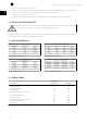
1.7.1 Optional Unit Size 6x components
Units are manufactured in different configurations due to the optional com-
ponents available. Depending on the unit configuration, optional equipment
may be mounted in the inverter, rectifier or option cabinet. The table below
lists the components available and the cabinet where it is factory installed.
Optional Component Cabinet Location
Mains Options
AC fuse Rectifier or inverter
Disconnect Option
A1 RFI filter Option
Load share Rectifier
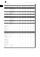
1.8 Tools Required
Operating Instructions for the Drives Series Frequency Converter
Metric socket set 7–19 mm
Socket extensions 100 mm–150 mm (4 in and 6 in)
Torx driver set T10 - T50
Torque wrench 0.675–19 Nm (6–170 in-lbs)
Needle nose pliers
Magnetic sockets
Ratchet
Hex wrench set
Screwdrivers Standard and Philips
Additional Tools Recommended for Testing
Digital volt/ohmmeter (must be rated for 1200 VDC for 690 V units)
Analog voltmeter
Oscilloscope
Clamp-on style ammeter
Test cable p/n 6KAF6H8766
Signal test board p/n 6KAF6H8437
Power supply: 610 - 800 VDC, 250 mA to supply external power to 4
power cards and the control card.
Power supply : 24 VDC, 2 A for external 24 V power supply.
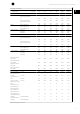
1.9 General Torque Tightening Values
For fastening hardware described in this manual, the torque values in the table below are used. These values are not intended for SCR, diode, or IGBT fasteners.
See the instructions included with those replacement parts for correct values.
Shaft Size Driver Size Torx / Hex Torque (in-lbs) Torque (Nm)
M4 T-20 / 7 mm 10 1.0
M5 T-25 / 8 mm 20 2.3
M6 T-30 / 10 mm 35 4.0
M8 T-40 / 13 mm 85 10
M10 T-50 / 17 mm 170 19
M12 18 mm / 19 mm 170 19
Table 1.7: Torque Values Table
High Power Service Manual for Unit Sizes 6x
9
1