
Instruction Manual


1. Disconnect mains prior to inspection or making repairs.
2. DO NOT touch electrical parts of frequency converter when connected to mains. After removing power from mains, wait 40 minutes before touching
any electrical parts. See the label on the front of the frequency converter door for specific discharge time.
3. The STOP key on the keypad does not disconnect mains.
4. During operation and while programming parameters, the motor may start without warning. Activate the STOP key when changing data.
1.4 Electrostatic Discharge (ESD)
When performing service, use proper ESD procedures to prevent damage to sensitive components.
Many electronic components within the frequency converter are sensitive to static electricity. Voltages so low that they cannot be felt, seen or heard can reduce
the life, affect performance, or completely destroy sensitive electronic components.
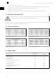
1.5 Unit Size Definitions
AF-600 FP 380-480 VAC Power
kW @400 VAC HP @460 VAC
Unit Size
500 650 61 / 63
560 750 61 / 63
630 900 62 / 64
710 1000 62 / 64
800 1200 62 / 64
1000 1350 62 / 64
Table 1.1: AF-600 FP 380-480 VAC
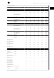
AF-650 GP 380-480 VAC Power
kW @400 VAC HP @460 VAC
Unit Size
450/ 500 600/ 650 61 / 63
500 / 560 650 / 750 61 / 63
560/ 630 750 / 900 62 / 64
630 / 710 900 / 1000 62 / 64
710 / 800 1000 / 1200 62 / 64
800 / 1000 1200 / 1350 62 / 64
Table 1.2: AF-650 GP 380-480 VAC
AF-600 FP 525-690 VAC Power
kW @550 VAC HP @575 VAC kW @690 VAC
Unit Size
560 750 710 61 / 63
670 950 800 61 / 63
750 1050 900 61 / 63
950 1150 1000 62 / 64
1000 1350 1200 62 / 64
1100 1550 1400 62 / 64
Table 1.3: AF-600 FP 525-690 VAC
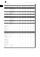
AF-650 GP 525-690 VAC Power
kW @550 VAC HP @575 VAC kW @690 VAC
Frame Size
500 / 560 650 / 750 630 / 710 61 / 63
560 / 670 750 / 950 710 / 800 61 / 63
670 / 750 950 / 1050 800 / 900 61 / 63
750 / 850 1050 / 1150 900 / 1000 62 / 64
850 / 1000 1150 / 1350 1000 / 1200 62 / 64
1000 / 1100 1350 / 1550 1200 / 1400 62 / 64
Table 1.4: AF-650 GP 525-690 VAC
1.6 Ratings Tables
DC Voltage Levels
380-480V &
380-500V units 525-690V units
Inrush Circuit Enabled 370 550
Inrush Circuit Disabled 395 570
Inverter Undervoltage Disable 373 553
Undervoltage Warning 410 585
Inverter Undervoltage Re-Enable (warning reset) 413 602
Overvoltage Warning (w/o Brake) 817 1084
Dynamic Brake Turn-on 810 1099
Inverter Overvoltage Re-Enable (warning reset) 821 1099
Overvoltage Warning (with Brake) 828 1109
Overvoltage Trip 855 1130
High Power Service Manual for Unit Sizes 6x
6
1