GE Consumer & Industrial Electrical Distribution AF-650 GPTM & AF-600 FPTM OPCEIP EtherNet/IP Operating Instructions The instructions do not purport to cover all details or variations in equipment nor to provide for every possible contingency to be met in connection with installation, operation or maintenance. Should further information be desired or should particular problems arise which are not covered sufficiently for the purchaser’s purposes, the matter should be referred to the GE company.
OPCEIP EtherNet/IP Contents 1 Safety 3 Safety Note 3 Safety Regulations 3 Warning against Unintended Start 4 2 Introduction 5 About this Manual 5 Technical Overview 5 Assumptions 5 Hardware 5 Background Knowledge 5 ODVA Conformance 6 Abbreviations 6 3 How to Install 7 Installation 7 The EtherNet/IP Option 7 How to Install Option in Frequency Converter 8 LED Behaviour 9 Topology 10 Network 11 Recommended Design Rules 12 EMC Precautions 13 4 How to Configure 15 IP
OPCEIP EtherNet/IP ODVA Control Profile 27 Control Word under Instances 20/70 and 21/71 28 Status Word under Instances 20/70 and 21/71 29 Reference Handling 29 Bus Speed Reference Value under Instances 100-101-103/150-151-153 29 Bus Speed Reference Value under Instances 20/70 and 21/71 31 6 Parameters Parameter Group O-## 33 Parameter Group EN-## 37 O-## Options/Comms 45 EN-## EtherNet 46 Data Types 47 Data Types Supported by AF-650 GP/AF-600 FP 47 7 Troubleshooting 49 Step-by-step
OPCEIP EtherNet/IP 1 Safety 1.1.1 Copyright, Limitation of Liability and Revision Rights 1 This publication contains information proprietary to GE. By accepting and using this manual the user agrees that the information contained herein will be used solely for operating equipment from GE or equipment from other vendors provided that such equipment is intended for communication with GE equipment over an Ethernet serial communication link.
OPCEIP EtherNet/IP 1.1.4 Warning against Unintended Start 1 1. The motor can be brought to a stop by means of digital commands, bus commands, references or a local stop, while the frequency converter is connected to mains. If personal safety considerations make it necessary to ensure that no unintended start occurs, these stop functions are not sufficient. 2. 3. While parameters are being changed, the motor may start. Consequently, the [OFF] key must always be activated.
OPCEIP EtherNet/IP 2 Introduction 2.1.
OPCEIP EtherNet/IP 2.1.6 ODVA Conformance The EtherNet/IP option is tested to conform to the ODVA standards, and is certified, towards conformance test level version 3. 2 2.1.
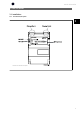
OPCEIP EtherNet/IP 3 How to Install 3.1 Installation 3.1.1 The EtherNet/IP Option 3 OCPEIP . / . Illustration 3.
OPCEIP EtherNet/IP 3.1.2 How to Install Option in Frequency Converter Items required for installing a network option in the frequency converter: - The network option - Network option adaptor frame for the AF-650 GP/AF-600 FP. This frame is deeper than the standard frame, to allow space for the network option beneath - Strain relief (only for unit sizes 11 and 12) 3 Instructions: - Remove Keypad panel from the AF-650 GP/AF-600 FP. - Remove the frame located beneath and discard it.
OPCEIP EtherNet/IP 3.1.3 LED Behaviour The option has 3 bi-coloured LEDs according to ODVA specifications: Description LED Label MS Module Status NS1 Network Status Ethernet Port 1 NS2 Network Status Ethernet Port 2 3 The option LED’s operates according to ODVA specifications.
OPCEIP EtherNet/IP 3.1.4 Topology The OPCEIP features a build-in Ethernet-switch, thus having two Ethernet RJ-45 connectors. This enables the possibility for connecting several EtherNet/IP options in a line topology as an alternative to the typical star-topology. The two ports are equal, in the sense that they are transparent for the option. If only one connector is used, either port can be used. 3 Illustration 3.2: Star topology Illustration 3.
OPCEIP EtherNet/IP NB! Please observe that mounting drives of different power-sizes in a line topology may result in unwanted power-off behaviour. Smaller drives discharge faster than bigger drives. This can result in loss of link in the line topology, which may lead to control word timeout. To avoid this, mount the drives with the longest discharge time first in the line topology. 3 Illustration 3.
OPCEIP EtherNet/IP 3.1.6 Recommended Design Rules While designing Ethernet networks special attention and caution must be taken regarding active network components. While designing a network for line topology it is important to notice that a small delay is added with each every switch in the line. It is not recommended to connect more than 32 drives in a line at any API. Exceeding the recommended design rules, may result in failing communication.
OPCEIP EtherNet/IP 3.1.7 EMC Precautions The following EMC precautions are recommended in order to achieve interference-free operation of the Ethernet network. Additional EMC information is available in the AF-650 GP/AF-600 FP series Design Guide. NB! Relevant national and local regulations, for example regarding protective earth connection, must be observed.
OPCEIP EtherNet/IP 4 14
OPCEIP EtherNet/IP 4 How to Configure 4.1.1 IP Settings All IP-related parameters are located in parameter group EN-##: EN-00 IP Address Assignment EN-01 IP Address EN-02 Subnet Mask EN-03 Default Gateway EN-04 DHCP Server EN-05 Lease Expires EN-06 Name Servers EN-07 Domain Name EN-08 Host Name EN-09 Physical Address 4 The OPCEIP option offers several ways of IP address assignment. Setting up drive with manual assigned IP address: Par.
OPCEIP EtherNet/IP Par. EN-03, Default Gateway is optional and only used in routed networks. Par. EN-06, Name Servers Par. EN-07, Domain Name Par. EN-08, Host Name Are used with Domain Name Server systems and are all optional. If DHCP or BOOTP is selected as IP address assignment, these parameters are read only. NB! It is only possible to assign valid class A, B and C IP address to the option. The valid ranges are shown in the below table: 4 Class A 1.0.0.1 - 126.255.255.254 Class B 128.1.0.1 - 191.
OPCEIP EtherNet/IP 4.1.3 Configuring the Scanner EDS file GE provides a generic English EDS (Electronic Data Sheet) file covering all voltage and power sizes, for off-line configuration. The EDS file can be downloaded from: www.geelectrical.com/drives NB! The current version of the major EtherNet/IP configuration tools does not support EDS-files for EtherNet/IP devices.
OPCEIP EtherNet/IP 4 The Module Info – This tap holds generic information. The Reset Module – This button will make a simulated Power-cycle of the drive. NB! For more information on the CIP class 1 Forward Open command, please refer to section: EtherNet/IP Connections under the How to Control -chapter.
OPCEIP EtherNet/IP 4.1.4 IP traffic The use of Ethernet based network for industrial automation purposes, calls for careful and thorough network design. Especially the use of active network components like switches and routers requires detailed know-how about the behaviour of IP traffic. Some important issues: Multicast Multicast traffic; is traffic that is addressed to a number of recipients. Each host processes the received multicast packet to determine if it is the target for the packet.
OPCEIP EtherNet/IP 5 20
OPCEIP EtherNet/IP 5 How to Control 5.1 How to Control 5.1.1 I/O Assembly Instances I/O Assembly Instances are a number of defined process control objects with defined content comprising control and status information. Unlike DeviceNet it is possible to run with asymmetrical instances. E.g. 101/153 = 8 bytes/20 bytes. It is not possible to mix instances across profiles, e.g. 20/100. Assembly instances must be consistent to the: ODVA or Drive profile. The controlling instance can be read in par.
OPCEIP EtherNet/IP NB! Use of 32-bit process data. For configuration of a 2-word (32-bit) parameter read/write, use 2 consecutive arrays in par. EN-21 and EN-22, like [2]+[3], [4]+[5], [6]+[7] etc. Read/write of 2word values in arrays like: [3]+[4], [5]+[6], [7]+[8] are not possible. 5.1.2 EtherNet/IP Connections The OPCEIP option supports the CIP connections described in the following sections: 5.1.3 Class 1 connection 5 I/O connection using TCP transport.
OPCEIP EtherNet/IP 5.1.4 Class 3 connection Cyclic connection using UDP transport. Maximum 6 Class 3 connections are supported. This type of connection is used for explicit messaging. The connection is established with a Forward Open command, containing the following information: Connection Name: Given name for the connection Message Parameters - Service Code - Class - Instance - Attribute - Member - Request Data 5 5.1.
OPCEIP EtherNet/IP 5.1.7 Change of State, COS The event controlled operation mode is used to minimize network traffic. Messages are transmitted only if a defined state or value has changed. The condition for triggering a COS message, is determined by the insertion of COS-filters (par. EN-38), for each bit in the different PCD-words. The filter acts like a logical AND-function: If a bit in the filter is set to “1”, the COS-function triggers when there is a change to the corresponding bit for the PCDword.
OPCEIP EtherNet/IP 5.2 GE Drive Control Profile 5.2.1 GE Drive Control Profile Control Word according to Drive Profile. Instances 100, 101, 103/150, 151, NB! 153 In par. O-56 Preset Reference Select select a selection is made to define how Bit 00/01 gates with the corresponding function on the digital inputs. Bit 02, DC brake: → Bit 02 = ‘0’ leads to DC braking and stop. Braking current and duration are set in par. B-01 DC Brake Current and par. B-02 DC Braking Time.
OPCEIP EtherNet/IP Bit 07, Reset: Bit 15 Reverse: Bit 07 = ‘0’ no reset. Bit 07 = ‘1’ resets a trip. Reset is activated on the leading Bit 15 = ‘0’ causes no reversing. Bit 15 = ‘1’ causes reversing. Note: In the edge of the signal, i.e. when changing from logic ‘0’ to logic ‘1’. factory setting reversing is set to digital in par.O-54 Reversing Select. Bit 15 Bit 08, Jog: selected. causes reversing only when Ser.
OPCEIP EtherNet/IP 5.2.2 Status Word according to (STW) Bit 07, No warning/Warning: Bit 07 = ‘0’ means that there are no warnings. Bit 07 = ‘1’ means that a warning → has occurred. Bit 08, Speed≠ reference/Speed = reference: Bit 08 = ‘0’ means that the motor is running, but that the present speed is different from the preset speed reference. For example, this might occur while the speed is being acceled/deceled during start/stop. Bit 08 = ‘1’ means that Illustration 5.2: (par.
OPCEIP EtherNet/IP 5.3 ODVA Control Profile 5.3.1 Control Word under Instances 20/70 and 21/71 Set par.O-10 Control Word Profile to ODVA. The control word in Instances 20 and 21 is defined as follows: → 5 NB! Bits 00 and 02 in Instance 20 are identical with bits 00 and 02 in the more extensive Instance 21.
OPCEIP EtherNet/IP Bit 6, Net Reference: Bit 6 = "0" Reference is from the standard inputs. Bit 6 = "1" Reference is from EIP. NB! Please note that changes will affect par. F-01 Frequency Setting 1 to par. C-34 Frequency Command 3. For the Speed reference, see section Bus speed reference value under Instances 20/70 and 21/71. 5.3.
OPCEIP EtherNet/IP 5.4 Reference Handling 5.4.1 Bus Speed Reference Value under Instances 100-101-103/150-151-153 In Drive-Profile (par. O-10 = [0] Drive profile) the reference is scaled as a normalized relative value in percent. The value is transmitted in hexadecimal: 0% = 0hex 100% = 4000hex -100% = C000hex Depending of the setting of par. F-50 Reference Range, the reference is scaled from – Max. to + Max. or from Min. to Max. 5 The actual reference [Ref.
OPCEIP EtherNet/IP 5.4.2 Bus Speed Reference Value under Instances 20/70 and 21/71 → The speed reference value should be transmitted to the drive in the form of a 16-bit word. The value is transmitted directly in RPM.
OPCEIP EtherNet/IP 6 32
OPCEIP EtherNet/IP 6 Parameters 6.1 Parameter Group O-## O-01 Control Site Option: Function: The setting in this parameter overrides the settings in par.O-50 Coasting Select to par.O-56 Preset Reference Select. [0] * Digital and ctrl.word Control by using both digital input and control word. [1] Digital only Control by using digital inputs only. [2] Controlword only Control by using control word only.
OPCEIP EtherNet/IP [7] Select setup 1 Changes the set-up upon reestablishment of communication following a control word time-out. If communication resumes causing the time-out situation to disappear, par.O-05 End-of-Timeout Function defines whether to resume the set-up used before the time-out or to retain the set-up endorsed by the time-out function.
OPCEIP EtherNet/IP O-14 Configurable Control Word CTW Option: Function: Selection of control word bit 10 if it is active low or active high [0] None [1] * Profile default [2] CTW Valid, active low O-50 Coasting Select Option: Function: Select control of the coasting function via the terminals (digital input) and/or via the network. [0] Digit Input Activates Start command via a digital input. [1] Bus Activates Start command via the serial communication port or network option module.
OPCEIP EtherNet/IP O-53 Start Select Option: Function: Select control of the drive start function via the terminals (digital input) and/or via the network. [0] Digit Input Activates Start command via a digital input. [1] Bus Activates Start command via the serial communication port or network option module. [2] Logic AND Activates Start command via the network/serial communication port, AND additionally via one of the digital inputs.
OPCEIP EtherNet/IP O-56 Preset Reference Select Option: Function: Select control of the drive Preset Reference selection via the terminals (digital input) and/or via the network. [0] Digit Input Activates Preset Reference selection via a digital input. [1] Bus Activates Preset Reference selection via the serial communication port or network option module. [2] Logic AND Activates Preset Reference selection via the network/serial communication port, AND additionally via one of the digital inputs.
OPCEIP EtherNet/IP EN-07 Domain Name Range: Blank Function: [0-19 characters] Domain name of the attached network. Can be automatically assigned when using DHCP. EN-08 Host Name Range: Blank Function: [0-19 characters] Logical (given) name of option. EN-09 Physical Address Range: Function: [00:1B:08:00:00:00 – 00:1B: Read only Displays the Physical (MAC) address of the option. 08:FF:FF:FF] EN-1# Ethernet Link Parameters 6 Option: Function: Applies for whole parameter group.
OPCEIP EtherNet/IP EN-20 Control Instance Range: Function: [None, 20, 21, 100, 101, 103] Read only. Displays the originator-to-target connection point. If no CIP connection is present “None” is displayed. EN-21 Process Data Config Write Range: Function: [[0 - 9] PCD read 0 - 9] Configuration of readable process data. NB! For configuration of 2-word (32-bit) parameter read/write, use 2 consecutive arrays in par. EN-21 and EN-22.
OPCEIP EtherNet/IP 6 [1651] Pulse Reference [1652] Feedback [Unit] [1653] Digi Pot Reference [1660] Digital Input [1661] Terminal 53 Switch Setting [1662] Analog Input 53 [1663] Terminal 54 Switch Setting [1664] Analog Input 54 [1665] Analog Output 42 [mA] [1666] Digital Output [bin] [1667] Freq. Input #29 [Hz] [1668] Freq. Input #33 [Hz] [1669] Pulse Output #27 [Hz] [1670] Pulse Output #29 [Hz] [1671] Relay Output [bin] [1672] Counter A [1673] Counter B [1674] Prec.
OPCEIP EtherNet/IP [3455] Curve Position [3456] Track Error [3457] Synchronizing Error [3458] Actual Velocity [3459] Actual Master Velocity [3460] Synchronizing Status [3461] Axis Status [3462] Program Status [3464] MCO 302 Status [3465] MCO 302 Control [3470] MCO Alarm Word 1 [3471] MCO Alarm Word 2 EN-28 Store Data Values Option: Function: This parameter activates a function that stores all parameter values in the non-volatile memory (EEPROM) 6 thus retaining parameter values at
OPCEIP EtherNet/IP EN-31 Net Reference Option: Function: Read only. Displays the reference source in Instance 21/71. [0] * Off Reference from the network is not active. [1] On Reference from the network is active. EN-32 Net Control Option: Function: Read only. Displays the control source in Instance 21/71. [0] * Off Control via the network is not active. [1] On Control via the network is active EN-33 CIP Revision Option: Function: Read only. Displays the CIP-version of the option software.
OPCEIP EtherNet/IP EN-89 Transparent Socket Channel Port Range: 0* Function: [0 – 9999] Configures the TCP port-number for the transparent socket channel. This enables Drive-messages to be sent transparently on Ethernet via TCP. Default value is 0, 0 means disabled. EN-90 Cable Diagnostics Option: Function: Enables/disables advanced Cable diagnosis function. If enabled, the distance to cable errors can be read out in par. EN-93.
OPCEIP EtherNet/IP EN-95 Broadcast Storm Filter Option: Function: Applies to par. EN-94; if the Broadcast Storm Protection should also include Multicast messages. [0] Broadcast only [1] Broadcast & Multicast EN-98 Interface Counters Option: Function: Read only. Advanced Interface counters, from build-in switch, can be used for low-level trouble-shooting, The parameter shows a sum of port 1 + port 2.
O-0# O-01 O-02 O-03 O-04 O-05 O-06 O-07 O-1# O-10 O-13 O-14 O-3# O-30 O-31 O-32 O-33 O-35 O-36 O-37 O-4# O-40 O-5# O-50 O-52 O-53 O-54 O-55 O-56 O-8# O-80 O-81 O-82 O-83 O-9# O-90 O-91 O-94 O-95 O-96 Par. No.
46 [0 - 1] [0 - 1] [0 - 2] [0 - 1] 20 - 103 [0 - 1] [0 - 1] 0000 - FFFF [0 - 1] [0 - 1] 0 - 99 9999 0 - 65535 0000 - FFFF [0 - 1] [0 - 1] [0 - 1] [0 - 1] [0 - 1] [0 - 1] [0 - 1] 0 - 200 Off - 20% [0 - 1] 0 - 65535 0 - 65535 No Link [0] 00:00:00:00 On [1] None [0] Full Duplex [1] None Off [0] Off [0] 0000 hex Off [0] Off [0] 00 0 0 0000 Disable [0] Disable [0] Disable [0] Disable [0] Disable [0] Enable [0] Enable [0] 0 0 Enable [1] 0 0 0 - 255 0 - 255 0 - 255 0 - 255 0 - 255 - Range 0 - 255 max. 19 ch.
OPCEIP EtherNet/IP 6.4 Data Types 6.4.1 Data Types Supported by AF-650 GP/AF-600 FP Conversion Index This number to the left refers to a conversion figure on the right to be used when writing or reading parameters. Conversion Index Conversion Factor 67 1/60 6 1000000 5 100000 4 10000 3 1000 2 100 1 10 0 1 -1 0.1 -2 0.01 -3 0.001 -4 0.0001 -5 0.00001 -6 0.
OPCEIP EtherNet/IP 7 48
OPCEIP EtherNet/IP 7 Troubleshooting 7.1.1 Step-by-step Troubleshooting Check: LEDs The option contains two LEDs to indicate the state of the device and the network. During normal operation the MS and at least one NS LED will show a constant green light.
OPCEIP EtherNet/IP Warnings All warnings within the frequency converter are represented by a single bit within a warning word. A warning word is always an action parameter. Bit status FALSE [0] means no warning, while bit status TRUE [1] means warning. Each bit status has a corresponding text string message. In addition to the warning word message the master will also be notified via a change in the status word. Alarms Following an alarm message the frequency converter will enter a fault condition.
OPCEIP EtherNet/IP Bit (Hex) Alarm word 2 (Par DR-91) Bit (Hex) Warning word (Par.
OPCEIP EtherNet/IP Bit (Hex) 7 Warning word 2 (Par. DR-93) Bit (Hex) Extended status word (Par.
OPCEIP EtherNet/IP Bit (Hex) Extended status word 2 (Par.
OPCEIP EtherNet/IP 8 54
OPCEIP EtherNet/IP 8 Appendix 8.1.1 Supported CIP Objects As in all implementations of CIP, EtherNet/IP shares the common Object Model. Objects are a common method to describe the specific application implemented in a device. Data is structured in Classes, Instances and Attributes: A class is a group of objects with the same structure. These groups of objects within a class are called instances. Every instance provides the same data elements called attributes.
OPCEIP EtherNet/IP Class ID 0x06 Connection Manager Attribute Access Name Data Type Description 1 Get Open Requests UINT Number of Forward Open requests received 2 Get Open Format Rejects UINT Number of Forward Open requests rejected due to bad format 3 Get Open Resource Rejects UINT Number of Forward Open requests rejected due to lack of resources 4 Get Open Other Rejects UINT Number of Forward Open requests rejected due to other reasons 5 Get Close Requests UINT Number of Forw
OPCEIP EtherNet/IP CIP Malfunction Code 0 Meaning Drive-Code Alarmword No alarm 0000 0000 CIP Malfunction Meaning No fault CIP Classification - 0 unused 0000 0001 No fault - 4210 Drive over temperature 0000 0002 Excessive Device Temperature mar 2240 Earth fault 0000 0004 Short to earth mau 0 unused 0000 0008 No fault - 8100 Controlword timeout 0000 0010 Communication mir 2310 Overcurrent 0000 0020 Continuous Overcurrent mau 8302 Torque limit 0000 0040 Torque limiting
OPCEIP EtherNet/IP Class ID 0x2A AC/DC Drive Object Attribute Access Rule Information about Data Type 1 Get Number of Attributes Supported USINT Contents 12 2 Get List of Attributes Supported USINT 3,4,6,7,8,18,19,20,21,22,28,29 3 Get At Reference Boolean Bit 8 of Drive STW 4 Get/Set Network Reference Boolean value written to parameter "Net Reference" Mapping of values from parameter H-40 6 Get/Set Drive Mode USINT 7 Get Actual Speed INT See Attribute 22 8 Get/Set Referenc
OPCEIP EtherNet/IP Class ID 0xF6 Link Object Three instances of the Link Object are implemented: - Instance 1 and 2 relates to the physical Port 1 and 2 of the option. - Instance 3 relates to the internal interface of the option, after the build-in switch. Attrib- Access ute Rule 1 Get Name Data Type Description of Attribute Parameter in drive Interface Speed UDINT Interface speed in Mbps (e.g., 0, 10, 100, 1000, etc.
OPCEIP EtherNet/IP Service Code Supported Class Service Name Description of Service Instance 01h Yes Yes Get_Attribute_All 0Eh Yes Yes Get_Attribute_Single Returns a predefined listing of this objects attributes Returns the contents of the specified attribute. 10h - Yes Set_Attribute_Single Modifies a single attribute. 43h - Yes Get_and_Clear Gets then clears the specified attribute (Interface Counters or Media Counters). Table 8.
OPCEIP EtherNet/IP Service Code Supported Class Service Name Description of Service Instance 0Eh Yes Yes Get_Attribute_Single 01h Yes Yes Get_Attributes_All returns contents of specified attribute returns predefined listing of object attributes 10h No Yes Set_Attribute_Single modifies attribute 4Bh No Yes Get_Enum_String reads enumerated strings from parameter instance Table 8.
OPCEIP EtherNet/IP Service Code Supported Class Service Name Description of Service Instance 0Eh Yes Yes Get_Attribute_Single returns contents of specified attribute 10h No Yes Set_Attribute_Single modifies attribute 4Bh No Yes Get_Att_Scattered returns specified parameter values 4Ch No Yes Set_Att_Scattered sets specified parameter values Table 8.
GE Consumer & Industrial Electrical Distribution AF-650 GPTM & AF-600 FPTM OPCEIP EtherNet/IP Operating Instructions The instructions do not purport to cover all details or variations in equipment nor to provide for every possible contingency to be met in connection with installation, operation or maintenance. Should further information be desired or should particular problems arise which are not covered sufficiently for the purchaser’s purposes, the matter should be referred to the GE company.