User Guide for the Galaxy Pulsar Edge Family of System Controllers Product Manual Comcode CC848836981 Issue 3 October 2011
Notice: The information, specifications, and procedures in this manual are subject to change without notice. Lineage Power assumes no responsibility for any errors that may appear in this document. © 2011 Lineage Power All International Rights Reserved Printed in U.S.A.
Galaxy Pulsar Edge Power System Controller Table of Contents Table of Contents .............................................................................................................. 3 1 Introduction .................................................................................................................... 8 Overview ......................................................................................................................... 8 Key Features .......................................
Galaxy Pulsar Edge Power System Controller Plant .......................................................................................................................... 63 Batteries .................................................................................................................... 65 Alarms ....................................................................................................................... 66 Distribution ...............................................................
Galaxy Pulsar Edge Power System Controller 7 NE872A Remote Distribution Monitor and Control Module ................................ 120 Overview ..................................................................................................................... 120 Module Features.......................................................................................................... 120 Module Connector Definitions ...................................................................................
Galaxy Pulsar Edge Power System Controller SNMP Operations ....................................................................................................... 199 SNMP Configuration .................................................................................................. 199 Community Strings ..................................................................................................... 200 Issue History ....................................................................................
Galaxy Pulsar Edge Power System Controller Issue 3 October 2011 7
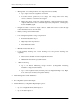
Galaxy Pulsar Edge Power System Controller 1 Introduction Overview The Galaxy Pulsar family of controllers is comprised of the Galaxy Pulsar Plus and Galaxy Pulsar Edge controllers. This manual covers the Galaxy Pulsar Edge group of power system controllers. These controllers were developed to be integrated into the power shelves of the Compact Power Line (CPL), Slimline Power Systems (SPS), CPS6000 Series II power systems, and the Infinity NE group of converter shelves.
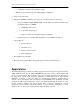
Galaxy Pulsar Edge Power System Controller ─ Management of four independent Low Voltage Disconnects (LVDs) Up to eight contactors assignable to the LVDs Load disconnects operated by low voltage, low voltage and/or time delay, remote command, or external control signal Battery disconnect operated by voltage threshold, voltage threshold and/or time, Adaptive Threshold, remote command, high battery temperature, or Emergency Power Off (EPO) signal ─ Integrated contactor control for single contactor
Galaxy Pulsar Edge Power System Controller ─ Combination of alarm inputs and alarm outputs *Number of inputs/outputs depends on Pulsar Edge configuration • Alarm output test feature • Integrated 10/100Base-T Ethernet for local port or for Network remote monitoring ─ Supports SNMP, TCP/IP, SMTP, HTTP, Telnet, FTP, and utilizes Dynamic Host Configuration Protocol (DHCP) SNMP Trap Test feature Community string support Remote software and configuration upgrade capability ─ Internal web server co
Galaxy Pulsar Edge Power System Controller Figure 1-1: Compact Power (CP) Line Shelves- CP841A Family of Controllers Figure 1-2: Small Power System (SPS) Line Shelves- SPS841A Family of Controllers Issue 3 October 2011 11
Galaxy Pulsar Edge Power System Controller Figure 1-3: CPS6000 Series II Power System (QS) Line Shelves- QS841E Family of Controllers Figure 1-4: Infinity NE Converter Power Shelves- QS841E and NE841A Family of Controllers Systems that utilize the Pulsar Edge controller provide a dedicated location for the controller that allows the maximum number of power modules to be used per shelf.
Galaxy Pulsar Edge Power System Controller the shelf. For details on these connections consult each of the product’s individual installation guides. The Galaxy Pulsar Edge controller provides controller configurations that have a front panel RS232 asynchronous Craft port or USB connection for local terminal access. The standard RS232 asynchronous Craft port connection is a DB9 but an RJ45 serial port connection is available in specific configurations.
Galaxy Pulsar Edge Power System Controller Customer Service Contacts Customer Service, Technical Support, Product Repair and Return, and Warranty Service For customers in the United States, Canada, Puerto Rico, and the US Virgin Islands, call 1-800THE-1PWR (1-800-843-1797). This number is staffed from 7:00 am to 5:00 pm Central Time (zone 6), Monday through Friday, on normal business days. At other times this number is still available, but for emergencies only.
Galaxy Pulsar Edge Power System Controller This page is intentionally blank.
Galaxy Pulsar Edge Power System Controller 2 Product Description Overview Lineage Power rectifiers accept alternating current (ac) power and rectify it to produce direct current (dc) power for powering external equipment (loads). Converters accept the dc output from rectifiers or other sources and convert it to various regulated output dc levels also needed for powering external equipment (loads). Batteries, generators, and UPS are typically used to provide backup power when ac is lost.
Galaxy Pulsar Edge Power System Controller Configurations The main “841” microprocessor board comprises the Pulsar Edge family of power system controllers. This controller is designed to fit a variety of systems and applications. Systems utilizing this controller are designed to allow the controller be quickly installed or removed from its allocated position through a simple thumb-screw or insertion fit without having to remove input output cable attachments to the unit.
Galaxy Pulsar Edge Power System Controller A listing of the Pulsar Edge controller options are defined in this section. Consult the controller ordering guide (Pulsar_Edge-AD) and sales for the most complete and up-to-date listing. The table below provides the basic naming nomenclature utilized for the different Pulsar Edge controller configurations. Below is the naming convention used by the Pulsar Edge product family.
Galaxy Pulsar Edge Power System Controller The following table identifies the controller configurations presently available. The information included in the “Description” column provides a brief description about the controller configuration.
Galaxy Pulsar Edge Power System Controller Specifications Table 2-2: Pulsar Edge Controller Specifications General Specification Item Input Power 48V: 36.5 volts to 60 volts 24V: 18.5 volts to 32 volts 5.0 watts maximum Input Power Connections Shelf powered. No external connection required; Front Panel Interface ─ Asynchronous RS232 or USB Craft Port ─ Two status LEDs ─ Options with LCD Interface System Configuration Methods ─ Front panel Craft port with T1.
Galaxy Pulsar Edge Power System Controller System Inputs/Outputs-Continued Plant Current Measurement Accuracy ±0.5% of full scale 0 to +50°C ±1.25% of full scale -40 to +85°C Resolution 1A Temperature Measurement Accuracy One-Wire Serial probes ±1°C -5 to +55°C ±3°C -40 to +85°C Resolution 0.
Galaxy Pulsar Edge Power System Controller 3 Safety Safety Statements Please read and follow all safety instructions and warnings before installing, maintaining, or repairing the system: • The Pulsar Edge controller platform is Underwriters Laboratories (UL) Listed per Subject Letter 1801, DC Power Distribution Centers for Telecommunications Equipment.
Galaxy Pulsar Edge Power System Controller Warning Statements and Safety Symbols The symbols may sometimes be accompanied by some type of statement; e.g., “Hazardous voltage/energy inside. Risk of injury. This unit must be accessed only by qualified personnel.” Signal words as described below may also be used to indicate the level of hazard. DANGER Indicates the presence of a hazard that will cause death or severe personal injury if the hazard is not avoided.
Galaxy Pulsar Edge Power System Controller Precautions When working on or using this type of equipment, the following precautions must be noted: • This unit must be installed, serviced, and operated only by skilled and qualified personnel who have the necessary knowledge and practical experience with electrical equipment and who understand the hazards that can arise when working on this type of equipment. • The power shelf that controller resides could be powered by multiple ac inputs.
Galaxy Pulsar Edge Power System Controller This page is intentionally blank.
Galaxy Pulsar Edge Power System Controller 4 Getting Started – Installation, StartUp, and Basic Configuration Preparation This section outlines the sequence for installing and quickly configuring the Pulsar Edge controller into a typical power system. A sample system will be illustrated here as an example but the individual installation start-up guides must be consulted for specific shelves. Some power system shelf configurations will be shipped from the factory with the controller pre-installed.
Galaxy Pulsar Edge Power System Controller Wiring Guidelines • All electrical connections must be made using the proper crimping tools and dies and must be torqued to standard or specified values. • All building wiring must comply with the NEC and other applicable local codes. • The temperature rating of the wire utilized must be no less than 90° Celsius and may be sized using the 90° Celsius ampacity table in the NEC handbook.
Galaxy Pulsar Edge Power System Controller Locate configuration jumpers for alarm relays on Edge-mounted controller. Loosen the chassis captive securing fastener and remove the controller from the shelf. Captive Fastening Screw Carefully remove the control unit from the shelf and locate the small opening in the chassis that allows external access to configuration jumpers. Alarm Output Configuration Jumpers Locate the jumpers for the alarm relays.
Galaxy Pulsar Edge Power System Controller 4 Configuring alarm relay contacts to “Open” or “Close” on alarm as required: Jumpers J20-25 configure the contact type provided at the system alarm interface for each respective Form-C alarm output present on the controller. Once the correct alarm jumper is located, carefully move each of respective configuration jumpers to the desired contact type: “Open On Alarm” or “Closed On Alarm” position as required.
Galaxy Pulsar Edge Power System Controller Locate and place the Pulsar Edge into its allocated position located to the left of the left-most rectifier slot. Although the physical configuration of the controller is different for the various product lines, the controller is located in a similar location. 7 Hold the controller by the controller’s chassis using the edges of the sheet metal to support the insertion. 8 Push the controller firmly into the shelf using the handle provided.
Galaxy Pulsar Edge Power System Controller Secure the controller in place by tightening the Philips captive fastening screw. Those with displays attached do not have a securing screw. The controller is now installed. 9 Connections to the Pulsar Edge Other than the front accessible serial or USB port, all connections to the Pulsar Edge Controller are made through backplane connections or appropriate cable assemblies to the controllers J1 interface.
Galaxy Pulsar Edge Power System Controller exact input and outputs available for a particular system. The following figures show the input and output connections for one of the available J2007001_L001 CP power shelf. Consult individual product Quick Start Guides for alarm input and output mapping and cable options.
Galaxy Pulsar Edge Power System Controller interface. If present, this operation can also be performed at the front panel at Main► Control/Operations. 6 The controller remembers certain previous system configurations and conditions. Nonexistent alarm conditions should clear. If the system LED is not green and the alarm LED is illuminated, review the installation procedure and refer to the troubleshooting section.
Galaxy Pulsar Edge Power System Controller Craft Port A GUI very similar to the interface provided by a LAN connection can be obtained locally through the RS232 or USB Craft port using EasyView 2.0, EV2. Once, EV2 has established the connection and is up and running the interface is the same as that provided over the LAN connection. The following describes connecting to the RS232 or USB Craft port using EasyView 2.0.
Galaxy Pulsar Edge Power System Controller Files\EasyView2\Drivers) and click on “Next >” button. The wizard will load the Lineage USB UART .inf file and the windows drivers needed to make the controller USB port appear as a virtual COM port on your PC. Click the “Finish” button to close the wizard. 3 Run the EasyView 2.0 executable EV2.exe to setup the program on your PC. Find and double click on EV2setup.exe. Click “Next >” at the “Welcome” window.
Galaxy Pulsar Edge Power System Controller Choose Destination Location, default is C:\Program Files\EasyView2, then click “Next>”. Backup Replaced Files. It is recommended that you do this if you have previously installed EasyView2, then click “Next >”. Select the components to be installed. Selecting all items is recommended. Selecting “CP841 Pulse Edge Support” will cover the various controller configurations including the CP841A, SPS841A, NE841A, and QS841E controllers. Then select “Next >”.
Galaxy Pulsar Edge Power System Controller Select the program manager group, then click “Next >”. The installer will install EasyView2 onto your PC. Click the “Finish” button to close the installer. Note: The driver (.inf file) for the Lineage USB UART is found in the \EasyView2\Drivers directory. This will be requested when the Windows detection that the controller USB port has been connected to the PC 4 Once the program is running a screen similar to the following should appear. Configure as required.
Galaxy Pulsar Edge Power System Controller It is not necessary to enter a “Username”. Enter one the appropriate password and click the Login button. There are three levels of access through the port; Read-Only, Read/Write, and Read/Write with password management privileges.
Galaxy Pulsar Edge Power System Controller A Home page similar to that follows should appear. This page should be nearly identical to that seen if the LAN access GUI was utilized. These pages are described in the next section of the manual. 6 Web Interface The Pulsar Edge integrated 10/100Base-T port supports standard protocols over TCP/IP like SNMP, TCP/IP, FTP and Telnet. It has an integrated HTTP web server that serves up web pages to remote PCs using standard web browsers.
Galaxy Pulsar Edge Power System Controller DHCP Client mode and the controller can be simply accessed by typing in its correct IP address. To access the system using the LAN as the Craft Port, follow the following basic procedures: 1 To use the Ethernet port locally as a Craft port the controller needs to be configured as a DHCP Server. First remove the controller from the shelf to place the controller into DHCP server mode.
Galaxy Pulsar Edge Power System Controller changing the mode of operation of the network port. This is achieved through the reapplication of power. When this process is performed the controller accepts the new Ethernet port configuration. The rebooting process takes approximately 2 minutes. 4 Attach the LAN cable between the controller’s LAN connection, RJ45 (J5), located at the rear of the shelf to the appropriate Ethernet port on the Craft PC.
Galaxy Pulsar Edge Power System Controller User security level: • Can view almost every parameter in the system • Can change only a few parameters considered to be of standard maintenance practices • Default password: lineage Super-User security level: • Can do everything the user can do • Can change any configuration parameter in the system (except passwords) • Default password: super-user Administrator security level: • Can do everything the super-user can do • Can change passwords • Can upgrade controll
Galaxy Pulsar Edge Power System Controller • • • • Flooded Lead Acid (Flooded) Lithium Metal Polymer (Li-LMP) Lithium ELiTE (Li-ELiTE) Nickel-Cadmium (Ni-Cd) Standard float values, alarm thresholds, and other functions are set as defaults for each of these battery types that can be modified in the field as desired. The Pulsar Edge also provides a list of industry standard batteries that are linked to these technologies and share the standard defaults.
Galaxy Pulsar Edge Power System Controller 5 Operation Overview The Pulsar Edge family of controllers provides system monitoring and control features for CP, SPS, and other Lineage Power rectifier based power systems. These controllers monitor and control system components including rectifiers and distribution modules via a multi-drop RS485 digital communications bus. System status, parameters, settings, and alarm thresholds can be viewed and configured from the controller’s front panel display.
Galaxy Pulsar Edge Power System Controller Figure 5-1: Galaxy Pulsar Edge Front Panel Display Assembly The previous s figure shows depictions of the front panel display in a 48V CPS6000 Series II rectifier system, a 48V Infinity NE-S converter output system, and a 48V SPS rectifier system. The display defaults with the system voltage (V) displayed on the main menu. Total system load (I) can be easily obtained by toggleling the display using ◄► either keys.
Galaxy Pulsar Edge Power System Controller Buttons Direction Buttons Parameter Change Display Contrast Description In the Menus, the ◄▲▼► direction buttons navigate to make a selection. A black box highlighting a menu item indicates that the item has sub-menus. When changing a system parameter, ▲▼ the buttons increase or decrease the value of the parameter. Contrast adjustment is also available through the menus at MenuConfigurationSystem Settings.
Galaxy Pulsar Edge Power System Controller Status LEDs The Pulsar Edge controller family provides two separate LED indicators that can be used to provide a high level first glance local indication at the site of the status of the power system and its monitored inputs. These LEDs can be configured to assist in providing more specific indications of the system status.
Galaxy Pulsar Edge Power System Controller Port Front Panel Serial Craft ports J6 Description A laptop PC can be connected to standard DB9 connector J6 to provide a ground-referenced RS-232 serial or to the available minis series-B USB connection on certain configurations for local craft access. EasyView 2 or the T1.317 command line can be used to facilitate this access. Controller with RS232 ports can also be configured and used with external modems.
Galaxy Pulsar Edge Power System Controller into the following categories: Alarms Warnings Status Control/Operations History Configuration Access to the main menu starts at the default front panel screen shown below. Front Panel Default Menu The front panel default screen displays the system DC output bus voltage. Using the◄► keys allows the system load current to be displayed. The operating mode of the system is also displayed.
Galaxy Pulsar Edge Power System Controller user with administrator level privileges. When the front panel PIN feature is enabled, the factory default for the PIN is 0000. Each position of the password is configurable between 0-9. A sample screen like that following is required for PIN access. The up, down, left and right arrows are used to enter the appropriate password.
Galaxy Pulsar Edge Power System Controller 3. 4. 5. 6. 7. 8. 9. 10. 11. 12. 13. 14. 15. 16.
Galaxy Pulsar Edge Power System Controller .
Galaxy Pulsar Edge Power System Controller Figure 5-3: Galaxy Pulsar Edge Control / Operations and History Menus Issue 3 October 2011 53
Galaxy Pulsar Edge Power System Controller Figure 5-4: Galaxy Pulsar Edge Configuration Menu (part 1) Issue 3 October 2011 54
Galaxy Pulsar Edge Power System Controller Figure 5-5: Galaxy Pulsar Edge Configuration Menu (part 2) Issue 3 October 2011 55
Galaxy Pulsar Edge Power System Controller Web Pages Using a standard browser or the EasyView 2 graphical user interface program provides the best mechanism for accessing the controller. All items accessible from the front panel are available through these interfaces. In addition, features like custom alarm mapping are available through the remote interfaces but is not available through the front panel. In general, front panel items are mapped over and are easily identified within the web page menu tabs.
Galaxy Pulsar Edge Power System Controller Maintenance Allows access to common operations performed during the maintenance or installation of the system or its components. Operations include restarting rectifiers/converters, starting alarm or battery tests, asserting boost, clearing history and statistics, clearing latched events and missing equipment, placing rectifiers/converters in and out of Standby, Reboot, and performing an SNMP Trap test. A T1.
Galaxy Pulsar Edge Power System Controller Installation This tab allows a quick configuration of the primary items needed to be set for a site. These basic items include: selecting the battery type, date, time, and the site ID. The Pulsar Edge can support two front panel languages. English, Spanish, French, and German are a few languages supported by the controller. Language support for web pages are will be available in the near future.
Galaxy Pulsar Edge Power System Controller Web Interface Menu Structure As with the front panel display, a map can be created for the items located in the web page tabs. Access to the main menu starts at the default Home screen described previously. The following figures provide a menu flow map for each primary tab. This information is followed up with brief descriptions of the items that show up in the screens.
Galaxy Pulsar Edge Power System Controller Figure 5-7: Maintenance Menu Issue 3 October 2011 60
Galaxy Pulsar Edge Power System Controller Figure 5-8: Settings Menu Issue 3 October 2011 61
Galaxy Pulsar Edge Power System Controller Figure 5-9: Installation and Software Menu Issue 3 October 2011 62
Galaxy Pulsar Edge Power System Controller Home Page The Home page provides an overview of the status of system components. Below are sample home screen shots from a Slim Line Power System (SPS) and an Infinity-C 663 converter shelf. The graphical representation of the plant changes as well as a few other parameters specifically concerning rectifiers and converters, respectively. This page is meant to provide an overall high level view of the system.
Galaxy Pulsar Edge Power System Controller controller installed generally have the plant configuration pre-configured from the factory. This display configuration can be modified as needed under the Settings►System►Plant and Installation►J or Product Code. In addition the following items are provided: Installed Rectifier/Converter Capacity Provides the total installed rectifier/Converter capacity in the system.
Galaxy Pulsar Edge Power System Controller Batteries The battery section of the page shows various status characteristics of the battery reserve system configured for the system. The following items are provided: Installed Capacity Total installed battery capacity based upon the number of strings in the system and the Amp-Hour (AH) rating of the strings installed. This data is automatically calculated.
Galaxy Pulsar Edge Power System Controller Temperature probes attached in the system. Lowest Temperature Lowest battery temperature being measured by the QS871 thermal probes attached in the system. Num Temp Probes Total number of installed QS871 thermal probes. Up to sixteen QS871 battery probes can be managed by the controller. Boost State Provides indication that the system is in the Boost state of operation. Possible modes are OFF, QRCT (Current terminated), MANUAL, and TIMED AUTO.
Galaxy Pulsar Edge Power System Controller LVBD Provides LVBD (Low Voltage Battery Disconnect) status. “None” is displayed for each non-configured contactor. “Closed” is shown for normal contactor state. “Open” shown for contactors that have opened and disconnected the battery. The summation of all shunts monitored by distribution monitoring boards ID1-ID8 that are assigned to battery or load current is shown. Configuring the centralized plant shunt as a battery shunt will also be the value shown here.
Galaxy Pulsar Edge Power System Controller Site Displays up to 20 configured characters entered for the Site Identification. Description Displays up to 55 characters entered for the Site Description. Primary Bus Displays the values of the system rectifier DC output bus voltage and output current (value to the load). The bus voltage is measure directly by the Pulsar Edge.
Galaxy Pulsar Edge Power System Controller Inventory Battery Discharge Provides a chronological view of up to the last 16 battery on discharge (BD) alarm events that have occurred since the last time the history log was cleared. In addition, 300 points are used to store battery discharge profiles. A typical discharge curve for a standard constant power load utilizes about 30 points a curve. Selecting Battery Discharge from the reports screen produces the following page.
Galaxy Pulsar Edge Power System Controller Statistics Basic statistics are stored for the plant load, battery temperature, and controller ambient temperature. Selecting Statistics from the reports screen produces a screen like the following: Highest Hourly At the change of each hour, the highest instantaneous value for the previous hour is compared with the three highest hourly maximums stored in memory.
Galaxy Pulsar Edge Power System Controller Highest Daily The instantaneous highest value readings, for each of the previous 16 days. Lowest Daily The instantaneous lowest value readings, for each of the previous 16 days. Highest Average (Daily) The highest one-hour average values, for each of the previous 32 days. Highest Average (Monthly) The monthly average of the daily maximum one-hour averages, for each of the previous 13 months.
Galaxy Pulsar Edge Power System Controller Boost History Provides a chronological view of up to the last 16 times the system entered boost mode since the last time the history log was cleared. Selecting Boost History from the reports screen produces the following page. Login History Login History provides a chronological view of the various login-in accesses experienced by the controller. These can be access through the local port, modem, or network.
Galaxy Pulsar Edge Power System Controller Login History Date/Time Application Action Port Chronological view of the last local terminal logins, Modem logins, and network accesses that have occurred since the last time the history log was cleared. The number of these events counts towards the total number of Modem, Network, and Local port events which can be up to 48 events. The date and time that a user connected or disconnected from the controller.
Galaxy Pulsar Edge Power System Controller Maintenance Page The following are the system control and operation functions that can be performed from the Maintenance page. These controls and operations are categorized as System, Data, Disconnects, and Rectifier operations. These operations are generally used in post installation and maintenance operations.
Galaxy Pulsar Edge Power System Controller System Maintenance Operations Lamp Test Restart Rectifiers Restart Converters Boost Start Battery Test Start Alarm Test Start SNMP Trap Test Remote Standby Load Defaults Temporarily illuminates all status indicators of attached rectifiers, distribution monitoring and control modules and the system controller. Provides the ability to restart all system serial controlled rectifiers at once.
Galaxy Pulsar Edge Power System Controller Clear History Clear Statistics Aborted, Redundancy Loss Alarm, and Converter Redundancy Loss. This operation is used to clear the various items that the controller maintains history records. Once cleared the controller begins to keep history of new events. All History Single command to clear all history. Alarm History Clears only alarm event history. BD History Clears only BD history. Rectifier History Clears only rectifier event history.
Galaxy Pulsar Edge Power System Controller T1.317 Terminal The maintenance page provides the user the ability to open a T1.317 command line session over the network. Clicking the button located at bottom of the page opens up a command-line session that allows a user to enter and execute specific T1.317 commands. Enter the specific T1.317 command at the allocated space and press the execute button. The controller will send its response in the area shown.
Galaxy Pulsar Edge Power System Controller CLI button Reboot The maintenance page provides a Reboot button that issues a T1.317 command line reboot command over the network. The controller will reboot upon receiving this command and connectivity will have to be reestablished. Settings Page The Settings page is where system operational parameters, system device information, and alarm thresholds are set-up and modified.
Galaxy Pulsar Edge Power System Controller System Configuration Pages System-Plant Configuration Items in the section shown below are thought of plant level configurations. The ability to assign the different alarm events severities, relays (if present), and to the LED is provided. Alarm events can be assigned Critical (CRIT), Major (MAJ), Minor (MIN), Warning (WRN), or Record Only (RO) severities. Submit must be used to save the changes.
Galaxy Pulsar Edge Power System Controller frame/bay would split the plant section on the Home page to show the number of frame/bays graphically, respectively. Note: The J or Product code selections found in the Installation section provide pre-configured configurations for the items in the list. System-Shunt Configuration Page Items here define the different shunts being monitored by the controller. One shunt, the Plant Shunt, is monitored directly by the Pulsar Edge.
Galaxy Pulsar Edge Power System Controller Plant Shunt Type Plant Shunt Rating Definition type for the on-board shunt used for centralized plant architectures that are designed with a single shunt to monitor load or battery current. The on-board shunt monitor may be configured as “NONE”, “BATTERY”, or “LOAD”. The factory default is Battery. Note: the shunt must be mounted in the grounded side of the system’s DC bus. Possible damage may occur if the shunt is connected incorrectly.
Galaxy Pulsar Edge Power System Controller ID8 Type: None Shunt: 600A IDs defined as None will have no currents displayed and shunt configuration has no affect. Note: Depending on the system and controller configuration for that system the values of the total load current (Iload) are calculated differently. The following table describes the different calculations for total load current.
Galaxy Pulsar Edge Power System Controller Shunt Type NONE System Configuration Proposed Controller Operation All battery management features shall be available. Shunt input may or may not be Controller shall report the following: connected to a shunt located in the ILoad = Σ IRect system. There are no “Shunt Monitors” Ibattery = Unavailable configured in the system. 1.
Galaxy Pulsar Edge Power System Controller Shunt Type System Configuration Proposed Controller Operation monitored is enabled, then the total battery current shall be calculated as follows: Ibattery = Unavailable ILoad = Σ ILoad shunt monitors Recharge current feature shall also be made unavailable. System-Contactor Configuration Page Items in this web page are used to define the different parameters and thresholds for managed Low Voltage Disconnect (LVD) contactors.
Galaxy Pulsar Edge Power System Controller (DCN01-DCN08) By default, these contactor controls are: LVBD (Low Voltage Battery Disconnect), LVLD1 (Low Voltage Load Disconnect 1), LVLD2 (Low Voltage Load Disconnect 2), and LVLD3 (Low Voltage Load Disconnect 3). The Pulsar Edge has assigned each unique board ID number as follows: ID1 to LVBD, ID2 to LVLD1, ID3 to LVLD2, and ID4 to LVLD3. Note: the text description used for the disconnect, such as “LVLD1”, can be renamed through the remote interfaces.
Galaxy Pulsar Edge Power System Controller LVLD3 (Disabled) Disconnect Mode (Voltage); Range: Voltage, Voltage/Time, None Disconnect Voltage (-42.0V); Range:-39.0 to -50.0V Time Delay (0 min); Range: 0-300min Reconnect Mode (Voltage); Range: Voltage, Voltage/Time, None Reconnect Voltage (-44.0V); Range: 39.0 to -55.
Galaxy Pulsar Edge Power System Controller and +14:00 Hrs:Mins. NTP address must be provided and controller rebooted for the Time Zone Offset to work properly. Enable Daylight Saving Temperature Units Clock Battery Low Clock Changed The factory default is 0:00 Hrs:Mins Enable or disable of automatic switch over with Daylight Saving. The factory default is Enabled. Selects between displaying temperature measurement in °C or °F. The factory default is °C.
Galaxy Pulsar Edge Power System Controller Reserve Pages Reserve-Battery Management Configurations Items in this section of the Settings pages are used to configure the various parameters associated with the battery reserve system. A sample screen shot follows along with parameter descriptions.
Galaxy Pulsar Edge Power System Controller Number Of Strings Battery Type String Capacity Enable Recharge Current Limit Recharge Current Limit Voltage Imbalance Issue 3 October 2011 The total number of battery string installed in the system. Uses for inventory purposes, state of charge, and initial reserve time calculations. Available range is 0-16 with factory default of zero strings for VRLAs.
Galaxy Pulsar Edge Power System Controller String End Of Discharge Voltage High Temperature Disconnect Battery On Discharge (BD) Float Battery On Discharge (BD) Boost Very Low Voltage Very High Battery Temperature High Battery Temperature Low Battery Temperature Very Low Battery Temperature Various Other Alarm Severities Valve-Reg batteries. This alarm is only generated after batteries have been sitting on float for a minimum of 12 hours and the total battery current is less than 3A.
Galaxy Pulsar Edge Power System Controller Enable Slope Thermal Compensation Nominal Temperature Upper Temperature Limit Step Temperature Upper Temperature Slope Enable Low Temperature Compensation Issue 3 October 2011 When Enabled it allows the controller to automatically adjust or compensate the system output voltage based upon the highest battery temperature monitored by the controller. This feature must be enabled in order to use High and or Low Temperature compensation.
Galaxy Pulsar Edge Power System Controller Lower Temperature Limit Low Temperature Slope Enable Battery Temp Probe-Fail Safe Slope Thermal Compensation feature must also be enabled in order to use Low Temperature compensation which is factory default disabled. Low Temperature Thermal Compensation Limit is the lower temperature thermal limit at which low temperature thermal compensation is stopped and the system DC voltage is no longer increased per configured linear slope rate.
Galaxy Pulsar Edge Power System Controller Factor the time duration of Boost. The value can be set from .1 to 9 with a factory default setting of .5. Current Threshold Configured battery current threshold during Boost that will end the Boost operation and return the system back to Float. The value can be set from 1 to 999 Amps with a factory default setting of 5 Amps. Pages with Boost Settings Provides a quick link to other pages with configuration items associated with Boost.
Galaxy Pulsar Edge Power System Controller Description Various Related Alarms Description field of up to 20 characters to describe the battery string connection for every monitoring input. The factory default for this description is String # Midpoint.
Galaxy Pulsar Edge Power System Controller Manual Test Type Automatic Test Type Rectifier Voltage During Test Timed Test Alarm Voltage Issue 3 October 2011 Selects between Disabled, 20%, Timed, and Amps-Hours Out test methods. When Disabled, battery test will not be permitted. 20% utilizes a patented algorithm that discharges the battery reserve by about 20% from the detection of a coup de fouet and calculates a reserve time.
Galaxy Pulsar Edge Power System Controller Reserve Time Low Real-Time Reserve Low This alarm threshold is checked only when batteries are considered in a stable state of charge. It is a coulomb count of charge current into the batteries that is compared to the Amp Hours configured in the controller. If no strings are entered this alarm is not generated. This feature is meant for capacity planning.
Galaxy Pulsar Edge Power System Controller Float Set Point Boost Set Point Float/Boost Internal High Voltage Shutdown Float/Boost Current Limit Rectifier On Threshold Enable Redundancy Number Of Redundant Rectifiers Remote Rectifier In Standby Enable Remote Group Standby Remote Group Standby Rectifiers Energy Efficiency Enable Issue 3 October 2011 Parameter sets the value that primary (rectifier) DC bus will be set and regulated. System Float Voltage set-point adjustable from -42.00V to 56.
Galaxy Pulsar Edge Power System Controller Efficiency Target Capacity Efficiency Turn On Capacity Inter-Rectifier Delay Initial Delay High Voltage Float and High Voltage Boost rectifier efficiency. Rectifiers that are not required to support the system’s present load based upon the configured Efficiency Target Capacity will automatically be placed into standby. The load will be constantly monitored and any rectifiers necessary to support additional load will be turned on.
Galaxy Pulsar Edge Power System Controller Fail Rectifier Fan Fail controller. The number of rectifiers required to report a rectifier failure is configurable based on the number of rectifiers in the system. The factory default for this threshold is 2. A single rectifier in the system has reported a rectifier fan failure to the controller. Power-Converter Configurations This section provides access to configure the various parameters, thresholds and alarms associated with the converters.
Galaxy Pulsar Edge Power System Controller Low Voltage Disconnect Disconnect Reconnect Voltage Alarms to and stored in the converters that is used by each converter for independent high voltage monitoring. The threshold can be set from 50.0V to -60.0V or +25.0 to +30.0V with a factory setting of -58.0V and +29.0V for 48V and 24V outputs, respectively. Enable or Disable for a feature that allows attached converters to be placed into Standby once an input voltage threshold is reached.
Galaxy Pulsar Edge Power System Controller Communication Passwords This section provides access to perform password administration. Administrator level access is required. There are three standard levels of access provide by the controller: User (Read Only), Super-User (Read/Write without password administration capabilities, and Administrator (Read/Write with password administration capabilities). The controller also has the ability to management User names and assigned passwords.
Galaxy Pulsar Edge Power System Controller interface using standard browsers such as Microsoft Internet Explorer®. It can provide plant alarm and control information to a distributed or centralized Network Operation Center (NOC) using the Simple Network Management Protocol (SNMP) or the Transaction Machine Language (TL1), which allow the Pulsar Edge to provide alarm information to the NOC for integrated network management.
Galaxy Pulsar Edge Power System Controller the Pulsar Edge’s port to be configured to operate plugged into the network. It can also be used in a “DHCP- Server” mode to provide Craft port functionality. In this mode the Pulsar Edge up 192.168.2.1 which should be used as the destination address in a user’s browser. Note: once this parameter is changed, the controller must be re-booted by removing power from the unit by removing and re-inserting the unit into the shelf.
Galaxy Pulsar Edge Power System Controller * These fields are automatically assigned when using the DHCP server or Client mode of operation and are generally required when utilizing a Static IP address setting. The controller provides configurable community strings for SNMP traps and Sets and Gets. Trap Community Strings Individual IP addresses and description configurations for up to four public community string alarm traps are provided.
Galaxy Pulsar Edge Power System Controller mechanism for transferring messages among separate hosts and browser applications. The protocol is used in Gateway for sending alarm messages and alerts through email. FTP FTP (file transfer protocol) is used to send files from one system to another under user commands. The protocol is used with the Pulsar Edge for downloading files and upgrades through a TCP connection.
Galaxy Pulsar Edge Power System Controller Alarm Call Out This page provides additional alarm call out support when using a Modem. Following is a sample screen. Alarm Notification This page provides the ability to assign specific alarms to specific SNMP trap location, email addresses, alarm relays (if present), and phone numbers. Clicking on a particular position will allow the configuration. Note the SNMP trap tests use the SNMP assignments from this screen. Following is a sample screen.
Galaxy Pulsar Edge Power System Controller UDE Notification The Pulsar Edge has the ability to create customized alarm events through a programming feature called User Define Events. Events that are programmed have the same configurable alarm parameters that show up and can be modified under the UDE Notification link. A sample screen is below. Alarm Cut Off This feature is reserved for a future implementation of an audible alarm.
Galaxy Pulsar Edge Power System Controller TL1 The Pulsar Edge has the ability to interface using the TL1 protocol. This screen allows the respective TL1 variables to be configured. A sample screen is below. Programming The Pulsar Edge has provides the ability to configure its alarms inputs as well as create user defined events and derived channels. The inputs available depend on the shelf configuration that the controller resides as well as the exact Pulsar Edge controller configuration.
Galaxy Pulsar Edge Power System Controller Following is a sample screen of a CP841A_3C3R. User Defined Events This page provides the ability to create specific events using the T1.317 variables and the basic mathematical operators to create a User Defined Event by creating a specific program line. Once the event is created it has the very similar configurable attributes as other basic controller alarms. Following is a sample screen.
Galaxy Pulsar Edge Power System Controller Installation - Minimum Configuration This section provides the minimum configuration required to get a site configured. It includes the Site ID (up to 12 characters), Site Description (Up to 55 characters), Date, Time, and the installed battery type. The “J-Code” for the shelf is used by the controller to define the web page view of the auxiliary inputs and generally should not be edited when the product is shipped from the factory.
Galaxy Pulsar Edge Power System Controller Software This section provides access to save a site’s configuration, restore a site configuration, and the ability to load or upgrade various controller software modules through the web page interface. Save Configuration Clicking on this link provides a self-explanatory path to perform a backup of the controller’s configuration to a “config.gal” file. The intention of this file is to store a sites entire configuration.
Galaxy Pulsar Edge Power System Controller Upgrade Software Issue 3 October 2011 Clicking on this link provides a path to upgrade the various software components in the controller. These include: Web pages, language file, application code, and custom factory defaults. Upgrading software goes through similar steps as restoring a configuration described above.
Galaxy Pulsar Edge Power System Controller 6 One-Wire Peripheral Devices QS873A Voltage/Thermal Probes The QS873A Voltage/Thermal Probes (VT-Probes) are used to measure battery temperatures for slope thermal compensation, and to provide mid-string voltages to the ES771 for battery voltage imbalance detection.
Galaxy Pulsar Edge Power System Controller J1 2-position connector serves to connect the VT-Probe to J2 on other VT-Probes in a daisy-chain fashion described above. Application QS873 VT Probes can be used with or without mid-string voltage monitoring. Only one probe is required to allow the battery slope thermal compensation function to be utilized. Additional probes for individual battery or multiple string monitoring can be added as desired.
Galaxy Pulsar Edge Power System Controller Step Action 4 5 Snap the cover closed on the VT-probe. Place the first probe to the negative battery post as shown in figure. 6 The controller automatically recognizes the VT-probes. The number of registered temperature probes and the highest battery temperature monitored may be checked from the front panel by scrolling down the menu at MenuStatusBatteries.
Galaxy Pulsar Edge Power System Controller ES771A Module Remote Mid-String Voltage Monitor The ES771A remote mid-string voltage monitoring module is used to measure the mid-string voltages of up to three strings of batteries. This unit utilizes an appropriate QS873A VT-Probe connection to obtain the voltage for measurement. It then serially transmits the appropriate information to the system controller which performs the voltage imbalance detection feature.
Galaxy Pulsar Edge Power System Controller ID Switch A seven-position rotary ID switch is used by the Pulsar Edge to uniquely address each ES771A in the system. A setting of “0” produces and invalid ID alarm. Valid ID settings are from 1 through 6. Units shipped from the factory have a factory default ID setting of “one”. Status LED The module illuminates its green LED when plugged into the 1-wire network and with the VTprobe attached to negative battery terminal of the mid-string voltage.
Galaxy Pulsar Edge Power System Controller Step 1 2 3 4 5 6 7 8 Action Insert one RJ-45 end of the 848652947 wire set into the P5-SYS AUX PORT on the controller and the other end to the first ES771A Remote Voltage Monitor module. Follow the steps for installing a probe described in the previous section to attach a VT probe to the negative post located at the center of the string as depicted in Figure 7.4. Do not cut the brown wire.
Galaxy Pulsar Edge Power System Controller Figure 6-5: Same System Monitored For Imbalance with VT Probe on Every Battery Following is a summary of the parts utilized in the 1-Wire management system. Consult quick start guides for the latest information. Probe And Cable Descriptions QS873A battery thermal probe QS873A_K4 battery thermal probe 10-ft Probe to Infinity NE interconnect 5-ft Probe to probe interconnect 10-ft Probe to probe interconnect ES771A Voltage Monitoring Module 2.
Galaxy Pulsar Edge Power System Controller 7 NE872A Remote Distribution Monitor and Control Module Overview Although the Pulsar Edge has the ability to directly control and manage a single LVD contactor with additional hardware. It can manage additional LVDs and distributions through the use of remote distribution monitor and control modules like the NE872.
Galaxy Pulsar Edge Power System Controller LEDs ( = On) Green Amber Red Condition Normal Minor Alarm Major Alarm Flashing Flash (5s) Communication Loss with Controller Manual Reconnect Command Accepting In addition, the following conditions will illuminate the LEDs as described below. This assumes the external disconnect switch is used to open and close the battery charging path to the batteries.
Galaxy Pulsar Edge Power System Controller mounted in the grounded or non-grounded side of the DC bus in a ±24V or -48V power system. The shunt must have a 50mV rating. Its current rating as well as its assignment to load or battery is configured at the controller. Three leads are used to monitor the shunt: Shunt+, Shunt-, and Shuntref. Shunt+ is the most positive side of the shunt input voltage as defined during a battery discharge.
Galaxy Pulsar Edge Power System Controller 12 10 Positive DC Systems J10 Negative DC Systems 3 1 Figure 7-3: NE872A ID Jumper Settings Connector Definitions The NE872 module has six connectors used for board power, measurement, alarm inputs and various serial communications. J1 Provides the connections to external distribution module’s bus voltage and power, shunt inputs and reference, Fuse Alarm Major And Open String Inputs.
Galaxy Pulsar Edge Power System Controller J2 Provides the contactor management interface for control and LVD status. Pin # Signal Name 1 LVD_COILA 2 LVD_C 3 LVD_NO 4 LVD_COILB 5 BATT_SNS 6 LVD _NC Signal Description Low Voltage Disconnect Coil Voltage A. “A” positive with respect to “B” to close contactor. Signal connected to one side of contactor coil. Common of contactor status indicator. Connect signal to Common of the micro-switch of contactor.
Galaxy Pulsar Edge Power System Controller J100 and J101 Pin # 1 2 3 4-8 Provides connectivity to the RS485 GP rectifier/converter bus as well as a pass through to the next RS485 connected device. Signal RS485+ RS485RS485REF Issue 3 October 2011 Signal Description B Inverting Driver Output / Inverting Receiver Input A Non-inverting Receiver Input/ Non-inverting Driver Output RS485 Reference/return. Pass-through on this board.
Galaxy Pulsar Edge Power System Controller 8 QS871A Remote Distribution Monitor and Control Module Overview Although the Pulsar Edge has the ability to directly control and manage a single LVD contactor without additional hardware. It can manage additional LVDs and distributions through the use of remote distribution monitor and control modules like the QS871.
Galaxy Pulsar Edge Power System Controller In addition, the following alarms will be issued for the conditions noted. This assumes the external disconnect switch is used to open and close the battery charging path to the batteries.
Galaxy Pulsar Edge Power System Controller case of loss of communication to the QS871As or failed or removed controller ). The configured disconnect and reconnect values assigned to a particular LVD function are sent from the controller to each respective QS871A. In the advent of a controller failure the QS871As will utilize their individual voltage monitoring and these thresholds to disconnect and reconnect the contactor.
Galaxy Pulsar Edge Power System Controller Edge controller and three connectors for monitoring circuit breakers, contactors and shunts. The connectors are defined as follows. J1 Provides the connections to external distribution module’s bus voltage and power, shunt inputs and reference, Fuse Alarm Major And Open String Inputs, and shunt. Pin # Signal Name 1 VPWR- 2 3 VPWR+ BATT- 4 SHUNT+ 5 SHUNT- 6 OS 7 FAJ 8 SHLF_ID3 J2 Pin # Signal Description VBUS(-) or BATT- Power.
Galaxy Pulsar Edge Power System Controller Note: The common or return of the micro switch for these signals shall be attached to Vbus- in the system outside of this board. J3 Connection that provides field access to External Auxiliary Fuse Alarm Major and the Remote LVD input. Pin # Signal Name 1 Remote LVD 2 3 Signal Description External contact closure for remote disconnecting attached LVD; Disconnects LVD on a dry contact closure to Remote LVD Return when feature is enabled.
Galaxy Pulsar Edge Power System Controller 9 Troubleshooting Table 9-A: Power System Troubleshooting Table Controller LED User Interface Display Rectifier LED Distribution Module Board LED Possible Problem(s) Possible Solution(s) AMBER MIN, AC Fail None GREEN Single Rectifier not receiving ac power. • AC input circuit breaker has opened. • AC input voltage is out of range. 1. Verify ac power to rectifier is available. 2. Verify rectifier input circuit breaker is closed. 3.
Galaxy Pulsar Edge Power System Controller Table 9-A: Power System Troubleshooting Table Controller LED User Interface Display Rectifier LED Distribution Module Board LED Possible Problem(s) Possible Solution(s) RED MAJ, Rectifier Fail (Note 1) AC OK DC OK AMBER (Blinking) One or both of the LVD contactors is open; someone may have manually opened LVD contactor. Place disconnect switch in ON position.
Galaxy Pulsar Edge Power System Controller Table 9-A: Power System Troubleshooting Table Controller LED Distribution Module Board LED User Interface Display Rectifier LED RED MIN, Rectifier Fail MAJ, Multiple Rectifier Fail MAJ, Battery on Discharge AC OK ALARM Normal Multiple rectifier thermal alarm: Excessive ambient temperature Multiple rectifier failure 1. Verify that there is no obstruction of the vertical airflow path. 2.
Galaxy Pulsar Edge Power System Controller Table 9-A: Power System Troubleshooting Table Controller LED GREEN User Interface Display Rectifier LED No Alarm, Individual Shunt Currents displayed at or above their maximum display values (≥600A for loads, ≥800A for battery) AC OK DC OK Distribution Module Board LED Normal Possible Problem(s) One or both of the QS871A shunt inputs is open-circuit. Possible Solution(s) 1.
Galaxy Pulsar Edge Power System Controller 10 Product Warranty A.
Galaxy Pulsar Edge Power System Controller D. If Seller has elected to repair or replace a defective Product, Customer shall have the option of removing and reinstalling or having Seller remove and reinstall the defective or nonconforming Product. The cost of the removal and the reinstallation shall be borne by Customer.
Galaxy Pulsar Edge Power System Controller Appendix A: Software Backup / Restore Through Network Connection Software can be upgraded through the 10/100Base-T connection either over the network or when the port has been configured to be used as an Ethernet Craft Port. There are four program files that can be upgraded on the Pulsar Edge: The boot block, the factory defaults, application, and web pages. Each of these items has a specific file name. FTP is used for upgrading controller software.
Galaxy Pulsar Edge Power System Controller directory. Each subdirectory contains files that are necessary for the Application Software and web pages. Thus, using an FTP client, shown previously, files may be transferred to/from these controller directories. The exact path to the upgrade file may be used in the “put” command to update the software. Note: software upgrades require administrator level privilege. Thus, the password required is administrator.
Galaxy Pulsar Edge Power System Controller Factory Defaults Using any FTP client, perform the following steps to load default web pages: 1. Type: FTP x.x.x.x ( The controller should have a Working IP Address of 192.168.2.1). ftp 192.168.2.1 Connected to 192.168.2.1 220 841 FTP Ready 2. Login as guest using the using the network administrator password (administrator). User (192.168.2.1:(none)): guest 331 User name okay, need password Password: administrator 230 Logged in 3.
Galaxy Pulsar Edge Power System Controller 4. Change directory (cd) to the code directory by typing: cd code. ftp> cd code 250 CWD command successful 5. Use the put command to copy the application software to the controller. ftp> put cp841-app.bin 200 Port command okay 150 Opening data connection for STOR (192.168.2.1,1576) 6. Wait until the message indicating a successful file transfer is displayed. 226 File sent OK ftp: 917504 bytes sent in 2.31Seconds 396.50Kbytes/sec. 7.
Galaxy Pulsar Edge Power System Controller Backup/Restore Configuration File Using any FTP client, perform the following steps to load default web pages: 1. Type: FTP x.x.x.x (The controller should have a Working IP Address of 192.168.2.1). ftp 192.168.2.1 Connected to 192.168.2.1 220 841 FTP Ready 2. Login as guest using the using the network administrator password (administrator). User (192.168.2.1:(none)): guest 331 User name okay, need password Password: administrator 230 Logged in 3.
Galaxy Pulsar Edge Power System Controller ftp: 917504 bytes sent in 2.31Seconds 396.50Kbytes/sec. 6. Type bye to exit the FTP session. ftp> bye 221 Goodbye! The software can also be uploaded through the web pages as described in Section 5. Login into through the web pages as “administrator” and go to the “Software” tab and use the appropriate easy to use tab: “Upgrade Software”, “Restore Configuration”, or “Backup Configuration”. A Sample screen shots are shown below.
Galaxy Pulsar Edge Power System Controller Appendix B: T1.317 Command Language Serial Access to the Pulsar Edge Controller RS-232 Terminal/Modem Port The Pulsar Edge is a highly flexible controller with many features. This section outlines programming the controller using the Hyper Terminal program that is shipped with most IBM compatible PC's. Connect the cable between the computer RS-232 port, and the Pulsar Edge System Controller RS-232 port, J6.
Galaxy Pulsar Edge Power System Controller command line prompts: User command-line prompt: * Super-user command-line prompt: ** When these prompts appear the controller is ready to accept commands. Note that the session will be terminated if the port is idle for 15 minutes. Introduction The Pulsar Edge command language is based on the T1.317 standard.
Galaxy Pulsar Edge Power System Controller following command: ope dc1,stt=“boost” The tables below summarize the object-attribute pairs in the system along with the commands that can be used with the pair and the valid range that the attribute may have. The values in bold text are the default settings for the attributes.
Galaxy Pulsar Edge Power System Controller PSM- Power System obj,attr description Related Commands sta cha ope ps1,fpe * ps1,fpt * Ps1,fpp * Front Panel Pin enable Front Panel Pin Time-out Front Panel Pin ps1,rss Restart all number ps1,ltt ps1,ast Lamp test System alarm state number Text ps1,slv ps1,dss Port security level Daylight saving start text d:d:d:d ps1,dse Daylight saving end d:d:d:d ps1,uet ps1,LEDL Uninstall Timeout List for LED alarm attribut
Galaxy Pulsar Edge Power System Controller obj,attr dc1,ide dc1,des dc1,typ dc1,vdc dc1,adc dc1,cap dc1,olcap dc1,trd dc1,sht description Description Description Plant Type Plant voltage Plant load current Total installed rectifier capacity Total on-line rectifier capacity Plant total rectifier drain Centralized plant shunt type sta cha dc1,sha dc1,stt dc1,bod Centralized plant shunt size Plant state Battery on discharge dc1,ems dc1,eme dc1,emt Efficiency state Efficiency
Galaxy Pulsar Edge Power System Controller DTA-Alarms With Two Thresholds obj,attr objid,fth objid,bth objid,acc objid,dly objid,noo objid,nor objid,nag objid,dst Description Alarm boost threshold Alarm float threshold Contact Closure Notify Delay Notify On Occur Notify On Retire NAG On Occur Notify Destination objid bda1 Description Battery On Discharge hfv1 High voltage hva1 Very high voltage THA-Alarms With One Threshold Related Command sta cha ope Float Thresho
Galaxy Pulsar Edge Power System Controller objid rrtl1 rtl1 rls1 vla1 Description Real-time reserve low Reserve time low Redundancy Loss Very low voltage SDA- Alarms With No Threshold Threshold 0-100hrs 0-100hrs 1-87 20-25.
Galaxy Pulsar Edge Power System Controller obj CNO4 COF1 COR1 DID1 EMD1 EPO1 EPR1 EXL1 FAJ1 FAN1 HCL1 ICR1 ISD1 LSF1 MAN1 MCM1 MDP1 MZD1 NNC1 OSA1 PFD1 PFS1 PGI1 PHT1 POR1 RFA1 RFN1 RIF1 SCD1 STF1 TPA1 VMF1 VSF1 ZID1 RMN-Rectifier Management obj,attr gm1,ide gm1,des gm1,lse gm1,rme gm1,fsd gm1,bsd gm1,fsp gm1,bsp gm1,fcl gm1,bcl gm1,oft gm1,wie Description Identifier Description Load Share Enable Redundancy monitor enable Float High Voltage Shutdown Boost High Voltage Shutdown Float Set-Point Boost Set-P
Galaxy Pulsar Edge Power System Controller REC-Rectifiers obj,attr gsr,des gsr,typ gsr,sn gsr,adc gsr,vdc gsr,stt Description Description Rectifier Type Serial number DC Current (VI, VIR) DC Voltage Individual rectifier state Related Commands sta cha ope gsr,cap gsr,aac gsr,vac gsr,tmp gsr,seq gsr,rfa gsr,acf gsr,man gsr,did gsr,clm gsr,rif gsr,rcf gsr,rfn gsr,lsf Capacity AC Current AC Voltage Temperature Use In Sequence Enable Rectifier Fail AC Fail Standby or Manual Off ID Conflict
Galaxy Pulsar Edge Power System Controller csr,adc csr,cap csr,stt DC Current Capacity State csr,cfa csr,did csr,ccf Converter Fail ID Conflict Communication Fail Number Number Text Number Number Number Number in amps Number in amps ON*, OFF, STANDBY*, MISSING, VACANT* ON qualifiers –LIM OFF qualifiers –LVD, -INF, -TA, -HVSD, -FAN 0=inactive 1=active 0=inactive 1=active 0=inactive 1=active s stands for shelf number (0 or 1) r stands for converter number (1 thru 6) * The user may onl
Galaxy Pulsar Edge Power System Controller BAR-Battery Reserve Management obj,attr br1,ntm br1,scd Description Number of temperatures present Battery voltage imbalance detection enable br1,scv Battery imbalance threshold BTD- Battery Type Definition Related Commands sta cha ope number number obj,attr btnn,des btnn,bty btnn,btc Description Description Battery Type Battery Class Related Commands sta cha ope btnn,cap Capacity type type Text Text Text Number Range of
Galaxy Pulsar Edge Power System Controller CNT- Disconnect Contactor Control obj,attr Description Related Commands sta cha ope type cnx,dtm Disconnect remaining time cnx,rth cnx,rdy cnx,ram Reconnect threshold Reconnect delay Reconnect automode cnx 4,rtm Reconnect remaining time number type number number number number text Range of Values 2= “VOLTAGE+TIME” >0 means going to disconnect 19.
Galaxy Pulsar Edge Power System Controller The contactor interface type defaults are as follows: DCN01 = CN1 DCN02 = CN2 DCN03 = CN3 DCN04-DCN08 = CN4 STC- Slope Thermal Compensation obj,attr sc1,ide sc1,des sc1,stt sc1,rve sc1,fse sc1,ltt sc1,ntt sc1,utt sc1,spt sc1,lsp sc1,usp Description Identifier Description State Raise Voltage Enable Probe Fail-Safe Enable Lower Temperature Threshold Nominal Temperature Threshold Upper Temperature Threshold Step Temperature Low temperature slope Upper temperature
Galaxy Pulsar Edge Power System Controller INP- Input Management obj,attr inmnn,pol Related Commands sta cha ope Description Input alarming state type text Range of Values "AUX1" – drives AUX1 alarm "AUX2" – drives AUX2 alarm “AUX3" – drives AUX3 alarm “AUX4" – drives AUX4 alarm “AUX5" – drives AUX5 alarm “AUX6" – drives AUX6 alarm "REMLVD" – Active signal opens battery contactors for built-in plant input, or for LVD inputs, it opens the contactor on the card where the signal is active.
Galaxy Pulsar Edge Power System Controller cm1,des cm1,ngi Description NAG Interval COP- Call-Out Phone Number text Number 30 char (Call-Out Manager) 15 to 60 minutes type text text text obj,attr x,des x,typ x,phn Description Description Type Phone Number Related Commands sta cha ope x,bdr Connect Baudrate Number x,dbt x,pry x,sbt x,dly x,pgr Data Bits Parity Stop Bits Pager ID Delay Pager ID (Pin #) Number Text Number Number Text x,msg Page
Galaxy Pulsar Edge Power System Controller address csn,wre Write enable number (255.255.255.
Galaxy Pulsar Edge Power System Controller LPT -Local RS-232 Port obj,attr Description Related Commands sta cha ope type lp1,dbt lp1,pry lp1,sbt lp1,tmo lp1,hsh lp1,app Data Bits Parity Stop Bits Time-Out Handshaking Application Number text Number Number text Text lp1,wre Write Enable Number ATS- Alarm Test obj,attr at1,des at1,stt at1,stg Description Description Alarm Test State Alarm Test Stage Related Commands sta cha ope at1,lte Alarm Test Enable
Galaxy Pulsar Edge Power System Controller Alarm Cut-off obj,attr aco1,jae aco1,jto aco1,nst aco1,nae aco1,nto aco1,lbe Description Major Alarm Cut-off Enable Major Alarm Cut-off Time-Out Minor Alarm Cut-off State Minor Alarm Cut-off Enable Minor Alarm Cut-off Time-Out Local Buzzer Enable UDE- User Defined Events Related Commands sta cha ope type Number Number Number Number Number Number Range of Values 0=disable 1=enable 1 to 8 hours 0=inactive 1=active 0=disable 1=enable 1 to 7
Galaxy Pulsar Edge Power System Controller dct1,des Description Text dct1,src Source Text TLM- TL1 Manager obj,attr tlm1,des tlm1,aue tlm1,cts tlm1,dsr Tlm1,prt Tlm1,tmo Description Description Activate-User Enable CTS Connect Detection DSR Connect Detection Port Timeout TL1- TL1 Object obj,attr tln,des tln,cds tln,aid tln,cnd tln,saf tln,rpt Description Description Condition Description Aid Condition Type Service Affecting Reporting CPT1 for DC converter load DC1 Trend Statistics CP1
Galaxy Pulsar Edge Power System Controller msnc,stt msnc,val msnc,did State Value Duplicate Id text Number Number Module n Channel c) None, Present, Missing Mid-String voltage 0=no 1=yes Where n is the Mid-String module number from 1 to 7, and c is the Mid-String channel number from 1 to 3 NET-Network Settings obj,attr net1,des Description Description Related Commands sta cha ope net1,ead net1,sor net1,dhcp Ethernet (MAC) Address DHCP server hardware override DHCP net1,ip
Galaxy Pulsar Edge Power System Controller ANET- Auxiliary Network Settings obj,attr net2,dom net2,msrv Description Static Domain Name Mail host IP Related Commands sta cha ope type text IP address Range of Values (not used if DHCP enabled) xxx.xxx.xxx.xxx (0.0.0.0 will force a DNS lookup of “mailhost”) net2 is currently only used by an attached Gateway Card in the NX400 system. Additional T1.
Galaxy Pulsar Edge Power System Controller bye Log-off Syntax: bye Description This command is used to terminate the session. cha Change Value Syntax: cha obj,attr=value where: obj,attr is an object-attribute pair. For example, ps1,sid. Description This command is used to change system configuration parameters. Examples are listed below to illustrate how this command works.
Galaxy Pulsar Edge Power System Controller This report gives the start date, start time, start reason, stop reason, and boost duration in minutes.
Galaxy Pulsar Edge Power System Controller This command is used to list all the rectifiers in the system. The command will list all present and missing rectifiers. Missing rectifiers are rectifiers that have been removed from a shelf. The cle will clear missing rectifiers from the controller's memory and they will no longer be listed by this command. Return value for a system with 3 rectifiers on shelf 1 would look like the following: * lis rec G11 G12 G13 .
Galaxy Pulsar Edge Power System Controller Description This command reports the value of the measurement, configuration, or control parameters in the system. A couple examples are listed below to illustrate how this command works. sta dc1,vdcReport plant voltage sta dc1,adcReport plant load current The command line would respond as follows for first command listed above. * sta dc1,vdc :DC1 VDC=-52.48 . *_ The “* ” in the example above is the user command line prompt.
Galaxy Pulsar Edge Power System Controller line is the end-of-command identifier. The “* ” in the example above is the user command line prompt. sum Report Plant Load Trend Statistics Syntax: sum dct1 Description This command reports the plant trend statistics, which includes up to 16 daily highest hourly and lowest hourly instantaneous readings, up to 32 daily maximum hourly averages, and up to 13 monthly averages of the daily maximum hourly averages.
Galaxy Pulsar Edge Power System Controller CLR=29-JUN-04,10:27:11 BEG=30-JUN-04,10:38:36 END=30-JUN-04,10:42:53 DUR=256 VAL= 0,51.08 8,50.18 18,49.24 20,48.87 248,48.36 252,49.76 254,50.84 256,51.13 . * The “.” line is the end-of-command identifier. The “* ” in the example above is the user command line prompt. GUI Report GUI Compatibility Syntax: GUI Description This command is for internal use only. It reports an EasyView compatibility number. The command response is: 841GUI=1.
Galaxy Pulsar Edge Power System Controller Error Message !-319, INVALID ATTRIBUTE !-320, INVALID OBJECT !328, FEATURE DISABLED !335, COULD NOT EXECUTE Issue 3 October 2011 Description An invalid object id was specified in the command or, a command referred to an attribute that doesn’t support it. An invalid object id was specified in the command An attempt was made to initiate a feature that is disabled. Command could not execute because of active alarms or a conflicting operation.
Galaxy Pulsar Edge Power System Controller Appendix C: Battery Functions Float Mode Float mode is the default operation mode of the power system. The system voltage, while in float mode, is determined by the configuration parameter Rectifier Float Set point (fsp) and may be adjusted by the Battery Thermal Compensation circuit, if active.
Galaxy Pulsar Edge Power System Controller Figure C-1: Slope Thermal Compensation The following describes the configuration parameters which may be Enabled/Disabled and configured by the user. Refer to Appendix D for the ranges of values the parameters may take and their factory default settings. Temperature Alarms The Pulsar Edge has several alarm thresholds that can be set based on temperature.
Galaxy Pulsar Edge Power System Controller • • • severity. Very High Temperature Alarm: The Very High Battery Thermal Alarm Threshold is a second alarm threshold available for high battery temperature. The monitored battery temperature at which above this threshold results in a Very High Battery Thermal alarm. This alarm threshold can be set from 30°C to 85°C and its severity is configurable. The alarm retires when the temperature drops to 10°C below the set threshold.
Galaxy Pulsar Edge Power System Controller rate that the controller utilizes to decrease the system DC voltage from the configured nominal temperature value to the High Temperature Compensation Limit. The high temperature slope setting (rate of decrease) can be set from -1mV to -10mV/oC per cell in -.1mV/oC per cell steps. The factory default is -3mV/oC per cell. • Nominal Temperature: The nominal temperature, shown as ntt, is the battery temperature which there is no battery voltage compensation.
Galaxy Pulsar Edge Power System Controller discharge and looks for the Coup de fouet in the discharge curve and runs the discharge for a time equal to about 20% of the system reserve capacity and calculates the remainder. • Amp-Hours Out: The test can be set to end when configured Amp-Hours to be removed has been reached. This test is also bound by the test duration timed parameter.
Galaxy Pulsar Edge Power System Controller • The test has continued for over 100 minutes. • The plant voltage has dropped below 44V or the LVD safe voltage. In this case, the system will abort the test and resume rectifier operation. After the test has stopped, the plant will revert to the float mode. It may go to boost mode if the auto-boost feature has been enabled.
Galaxy Pulsar Edge Power System Controller This feature may be used by customers to determine if the load being served is greater than N rectifiers worth, in an N+1 system. That is, the load requirements have changed such that the power system is no longer operating as a redundant power system. An additional rectifier may be required to ensure continuous redundant operation. More rectifiers may be required if more than N+1 redundancy is configured and required.
Galaxy Pulsar Edge Power System Controller Battery Parameter Defaults The Pulsar Edge controller has been configured with battery specific defaults. These battery types are shown in the top portion of Table B-1. The generic Valve-Regulated Lead Acid battery is the default battery type for this controller configuration. Battery models and their parameters can be added or adjusted in the field.
Galaxy Pulsar Edge Power System Controller Appendix D: Default Configurations Tables D-1through D-4 provide the default settings for the configurable parameters and features that are associated in the Pulsar Edge. Also listed are the battery technologies and specific battery models included in the configuration file previously shown in Appendix C. Specific battery models assume the configuration defaults for their generic technology class except for a specific capacity and model name.
Galaxy Pulsar Edge Power System Controller Table D-1: Standard Configuration Items Category Battery Type Definitions Description Battery 1 Type Description Factory Default Factory 24V Rectifier Default Factory 48V Rectifier Default Range Factory Factory 24V Factory 48V <=32 chars obj,attr "Generic Valve-Reg Battery" BT01,DES Battery 1 Type "Valve-Reg" BT01,BTY Battery 1 Class "VALVE-REG" BT01,BTC 0 BT01,CAP Battery 1 Capacity Battery 2 Type Description <=32 chars "Generic Flooded Ba
Galaxy Pulsar Edge Power System Controller Category Description Factory Default Factory 24V Rectifier Default Factory 48V Rectifier Default Range Factory Factory 24V Factory 48V <=32 chars "Lineage Power (407928753)" "IR40EC" Battery 11 Capacity Battery 12 Type Description 145 obj,attr BT11,CAP BT12,DES Battery 12 Type BT12,BTY Battery 12 Class "VALVE-REG" BT12,BTC 35 BT12,CAP "GNB-EXIDE (408406023)" BT13,DES Battery 13 Type "M12V105FT" BT13,BTY Battery 13 Class "VALVE-REG" BT13
Galaxy Pulsar Edge Power System Controller Category Description Range Factory Default Factory 24V Rectifier Default Factory 48V Rectifier Default Factory Factory 24V Factory 48V obj,attr "TEL12-105F" Battery 23 Type BT23,BTY Battery 23 Class Battery 23 Capacity Battery 24 Type Description <=32 chars "VALVE-REG" BT23,BTC 100 BT23,CAP "C&D (CC408634216)" "TEL12-90" BT24,DES Battery 24 Type BT24,BTY Battery 24 Class Battery 24 Capacity Battery 25 Type Description <=32 chars "VALVE-REG"
Galaxy Pulsar Edge Power System Controller Category Description Daylight Saving End Time zone offset Uninstall Equipment Timeout Critical Equals Major Factory Default Factory 24V Rectifier Default Factory 48V Rectifier Default Range Factory Factory 24V Factory 48V mon:wk:dow:min mon:-1:dom:min "11:1:0:120" PS1,DSE -840 - +840 minutes (±14 hours) 0 PS1,TZO 0 to 60s 15 PS1,UET 1=Enabled 0=Disabled 1 PS1,CEM "lineage" PAS U, User Password Super-user Password Administrator Password Low
Galaxy Pulsar Edge Power System Controller Category Description LV Load 2 Reconnect Voltage Load Disconnect 3 Factory 48V Rectifier Default Factory Factory 24V Factory 48V obj,attr 22.00 44.00 CN3,RTH 19.5 to 27 -39.0 to -55.
Galaxy Pulsar Edge Power System Controller Category Factory Default Factory 24V Rectifier Default Factory 48V Rectifier Default Range Factory Factory 24V Factory 48V Group Standby/Sequencing Enable 1=Enabled 0=Disabled 0 DC1,RSQ Remote rectifier Off Enable 1=Enabled 0=Disabled 1 PS1,RRF 1 to 80 1 RLS1,THR Multiple Rectifier Fail 2 to 88 2 MFA1,THR Oring FET test enable 1=Enabled 0=Disabled 1 GM1,OFT Efficiency Enable 1=Enabled 0=Disabled 0 DC1,EME Efficiency Target 20% to 95
Galaxy Pulsar Edge Power System Controller Category Factory Default Factory 24V Rectifier Default Factory 48V Rectifier Default Range Factory Factory 24V Factory 48V 0 to 9999 Amps 100 DCM01,SHA Battery/None /Load "NONE" DCM02,TYP 0 to 9999 Amps 100 DCM02,SHA Battery/None /Load "NONE" DCM03,TYP 0 to 9999 Amps 100 DCM03,SHA Battery/None /Load "NONE" DCM04,TYP 0 to 9999 Amps 100 DCM04,SHA Battery/None /Load "NONE" DCM05,TYP 0 to 9999 Amps 100 DCM05,SHA Battery/None /Load "
Galaxy Pulsar Edge Power System Controller Category Description Range Input 8 Type Factory 24V Rectifier Default Factory 48V Rectifier Default Factory Factory 24V Factory 48V obj,attr "AUX4" IN008,TYP Input 8 Active State CLOSED=Closed to RTN, OPEN=Open to RTN "CLOSED" IN008,POL Input 9 Description <=32 chars "Low External Ambient" IN009,DES "AUX5" IN009,TYP Input 9 Active State CLOSED=Closed to RTN, OPEN=Open to RTN "CLOSED" IN009,POL Input 10 Description <=32 chars "Fan Fail"
Galaxy Pulsar Edge Power System Controller Category Alarm Test Serial Communication Ports Factory Default Factory 24V Rectifier Default Factory 48V Rectifier Default Range Factory Factory 24V Factory 48V Auxiliary Alarm 5 Front Panel Desc <=24 chars "Low Ext Ambient" AUX5,FDS Auxiliary Alarm 6 Description <=32 chars "Fan Fail" AUX6,DES Auxiliary Alarm 6 Front Panel Desc <=24 chars "Fan Fail" AUX6,FDS Auxiliary Alarm 7 Description <=32 chars "Hydrogen Present" AUX7,DES Auxiliary Al
Galaxy Pulsar Edge Power System Controller Category Factory Default Factory 24V Rectifier Default Factory 48V Rectifier Default Range Factory Factory 24V Factory 48V 0-45 minutes 5 MP1,TMO ≤ 20 Characters "AT&FEV&C1S0=0H" MP1,INS 1 to 9 1 MP1,NRG No/SW/HW "NO" MP1,HSH 0=static 1=client 2=server 1 NET1,DHCP Static IP Address xxx.xxx.xxx.xxx "0.0.0.0" NET1,IP Static Subnet Mask xxx.xxx.xxx.xxx "0.0.0.0" NET1,SUB Static Gateway (Router) IP xxx.xxx.xxx.xxx "0.0.0.
Galaxy Pulsar Edge Power System Controller Category Factory 24V Factory 48V Factory Call-out Data Bits 7 or 8 8 COP,DBT Call-Out Parity n,e,o N COP,PRY Call-Out Stop Bits 1 or 2 1 COP,SBT 0 to 9 seconds 0 COP,DLY Pager ID up to 25 Characters "" COP,PGR Pager Message up to 25 Characters "" COP,MSG Phone Number up to 25 Characters "" PSO,PHN Baudrate 300, 1200, 2400, 4800, 9600, 19200 2400 PSO,BDR Data Bits 7 or 8 8 PSO,DBT Parity n,e,o N PSO,PRY Stop Bits 1 or 2
Galaxy Pulsar Edge Power System Controller Category Factory 48V Rectifier Default Factory 24V Factory 48V Range Factory Baudrate 4 300, 1200, 2400, 4800, 9600, 19200 2400 CBS,BR4 up to 25 Characters "" CBS,PH5 300, 1200, 2400, 4800, 9600, 19200 2400 CBS,BR5 "0.0.0.0" SND,IP 0=disable 1=enable SETs 0 CS1,WRE up to 20 Characters "public" CS1,STR Community String 1 IP Address xxx.xxx.xxx.xxx "0.0.0.0" CS1,IP Community String 1 IP Address Mask xxx.xxx.xxx.xxx "255.255.255.
Galaxy Pulsar Edge Power System Controller Table D-2: 48V Battery Related Items Category Voltage Settings Range Valve-Reg Flooded Li_ELiTE NiCd LiLMP obj,attr Rectifier Float Selective High Voltage Shutdown -50 to -60V 58.50 58.50 58.50 58.50 58.50 GM1,FSD High Float Voltage Major Alarm -50 to -60V 57.00 57.00 57.00 57.00 57.00 HVA1,FTH High Float Voltage Minor Alarm -50 to -60V 56.00 56.00 56.00 56.00 56.00 HFV1,FTH -42 to -56.5V 54.48 52.08 54.48 54.40 54.
Galaxy Pulsar Edge Power System Controller Category Battery Boost Range Valve-Reg Flooded Li_ELiTE NiCd LiLMP obj,attr Boost Rectifier High Voltage Shutdown -52 to -60V 58.50 58.50 58.50 58.50 58.50 GM1,BSD Boost High Voltage Major Alarm -50 to -60V 57.0 58.5 57.0 57.0 57.0 HVA1,BTH Boost High Voltage Minor Alarm -50 to -60V 56.0 58.0 56.0 56.0 56.0 HFV1,BTH Boost Voltage -48 to -58V 55.2 57.0 54.5 54.4 54.5 GM1,BSP Boost Battery on Discharge Alarm -46 to -55V 51.
Galaxy Pulsar Edge Power System Controller Category Battery Slope Compensation Range Valve-Reg Flooded Li_ELiTE NiCd LiLMP obj,attr Slope Thermal Compensation (STC) 1=Enabled 0=Disabled 0 0 0 0 0 SC1,STT High Temperature Voltage Step Down 45 to 85oC 113 to 185F 75 75 75 75 75 SC1,SPT High Temperature Compensation Stop 30 to 55oC 86 to 131F 55 55 55 55 55 SC1,UTT 3 3 3 3 3 SC1,USP Description o High Temperature Decrease Rate 1-10mV/ C per cell o Nominal Temperature
Galaxy Pulsar Edge Power System Controller Appendix E: Alarms and Relays Alarm Relays The Galaxy Pulsar Edge can be configured to provide up to six alarm relays depending on the controller configuration. Four alarm relays provide the alarm condition and two provide the overall system severity associated with the alarm. Presently, the maximum number of relays available in the Infinity NE841A and QS841E is six. The maximum number of relays in the CP841A and SPS841A controllers is five.
Galaxy Pulsar Edge Power System Controller SEVERITY RELAY Description CRIT PMJ Auxiliary 12 MAJ Auxiliary Major MAJ PMN WRN USER RELAYS RO R1 R2 R3 R4 LED SNMP ALM DST AUX12 AMJ1 Battery Test Active BTA1 RO Battery on Discharge (Float and Boost) Object ID MAJ R1 Battery Voltage (Cell) Imbalance Detect MIN Check Battery/Battery Test Failed MIN ALM BDA1 SCD1 BFA1 Clock Changed RO CLC1 Configuration Changed RO CCH1 Controller Fail (Not user mappable) x Converter Distr
Galaxy Pulsar Edge Power System Controller SEVERITY RELAY Description Major Communication Fail Alarm CRIT PMJ PMN WRN USER RELAYS RO R1 R2 R3 R4 LED SNMP ALM DST MCM1 MAJ Manual Off MIN Minor Communication Fail Alarm MIN Multiple AC Fail MAJ Multiple Converter Fail MAJ Multiple Manual Off MAJ Multiple Rectifier Fail MAJ Object ID MAN1 CMA1 MACF1 R3 CMFA1 R2 MMAN1 MFA1 R2 No Call-Out Response WRN COR1 No Dial-Out Response WRN POR1 Open String OSA1 MAJ Password A
Galaxy Pulsar Edge Power System Controller Appendix F: SNMP SNMP Overview In addition to supporting the basic protocols (Telnet, HTTP, FTP, and SMTP) on TCP/IP, the Pulsar Edge supports conveying system alarm and control information to a Network Operation Center (NOC) using the Simple Network Management Protocol (SNMP). SNMP is the most popular protocol for managing diverse networks.
Galaxy Pulsar Edge Power System Controller SNMP Operations Interactions between the SNMP Host and the SNMP Agent can be any of four different types of commands: Reads, Writes, Traversal operations, and Traps. SNMP utilizes six operations to respond to the various SNMP Hosts: Get, GetNext, GetBulk, Set, Trap, and Inform. The Pulsar Edge implements the Get, GetNext, Set, and Trap operations. Get - Allows the SNMP Host to retrieve a value from the SNMP Agent.
Galaxy Pulsar Edge Power System Controller Individual alarms or events are assigned as Traps to one of the four specific SNMP destinations. Assignment of the alarm and events is performed under the “Alarm Notification” link under the main configuration “Settings” tab. The sample screen for this configuration follows. Community Strings SNMP Community Strings can serve as trap destinations as well as passwords or user IDs for network elements.
Galaxy Pulsar Edge Power System Controller Issue History Issue 0.1 Release for internal review and comment. Issue 1.0 Release to production. Issue 2.0 Added display information, enhanced Web sections, added converter sections, added 24V rectifier operation and settings, corrected defaults, add various pictures. Issue 3.0 Strengthened ground bond (connection) note.