H2007001 G21 Series Infinity D Power System with -48 Volt Rectifiers, +24 Volt Converters, and Pulsar Controller Installation Guide Installation Guide LineagePower.com Comcode CC848853515 Issue 2.
Infinity D Power System Installation Guide: -48V Plants H2007001 Notice: The information, specifications, and procedures in this manual are subject to change without notice. Lineage Power assumes no responsibility for any errors that may appear in this document. © 2008 Lineage Power Systems, Inc. (Mesquite, Texas) All International Rights Reserved Printed in U.S.A.
Infinity D Power System Installation Guide: -48V Plants H2007001 Table of Contents 1. 2. 3. 4. 5. Introduction.............................................................................................................. 5 Document Objectives................................................................................................. 5 Audience .................................................................................................................... 5 Applications .......................
Infinity D Power System Installation Guide: -48V Plants H2007001 Troubleshooting VT-Probes..................................................................................... 74 6. Product Warranty.................................................................................................. 75 Appendix A: Pulsar Controller...................................................................................... 77 User Interface Overview ...................................................................
Infinity D Power System Installation Guide: -48V Plants H2007001 1. Introduction Document Objectives This manual provides installation and maintenance information for the Lineage Power Infinity D power system: • • • • • • Safety Information Product Description Installation Procedures Test and Acceptance Troubleshooting, including Controller and Rectifier Operations Product Warranty Audience • • Equipment Installers – Instructions for installation, test, and acceptance.
Infinity D Power System Installation Guide: -48V Plants H2007001 Customer Service Contacts Customer Service, Technical Support, Product Repair and Return, and Warranty Service For customers in the United States, Canada, Puerto Rico, and the US Virgin Islands, call 1-800-THE-1PWR (1-800-843-1797). This number is staffed from 7:00 am to 5:00 pm Central Time (zone 6), Monday through Friday, on normal business days. At other times this number is still available, for emergencies only.
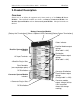
Infinity D Power System Installation Guide: -48V Plants H2007001 2. Product Description Overview Shown here is an Infinity D equipment only frame made up of six Infinity D Power Modules. Three different modules are shown: one Battery Connection Module, four Rectifier System Modules and one Converter System Module.
Infinity D Power System Installation Guide: -48V Plants H2007001 Battery Connection Module Batteries power the load equipment when ac input to the rectifiers is lost. The batteries are connected to the Battery Connection Module at the top of the frame. An optional Low Voltage Battery Disconnect (LVBD) contactor provides deep discharge protection if desired. The System Shunt also resides in the Battery Connection Module.
Infinity D Power System Installation Guide: -48V Plants H2007001 Infinity D Block Diagram Issue 2.
Infinity D Power System Installation Guide: -48V Plants H2007001 Note on AC surge protection requirements: Our rectifier product Safety Approval is performed to assure safe and reliable performance in IEC 60664-1 Installation Category II environments. Building AC surge protection devices installed prior to the rectifiers must provide this degree of protection. Issue 2.
Infinity D Power System Installation Guide: -48V Plants H2007001 3. Safety Safety Statements Please read and follow all safety instructions and warnings before installing, maintaining, or repairing the Lineage power system: • • • • • • • • • • • The CE Mark demonstrates compliance with the European Union Council Directives for Low Voltage and EMC. This system is Underwriters Laboratories (UL) Listed per Subject 1801, Power Distribution Centers for Telecommunications Equipment (UL 60950-1).
Infinity D Power System Installation Guide: -48V Plants • • • • • • • • • • • • • H2007001 Torque electrical connections to the values specified on labels or in the product documentation. Battery input cables must be dressed to avoid damage to the conductors (caused by routing around sharp edges or routing in areas where wires could get pinched) and undue stress on the connectors.
Infinity D Power System Installation Guide: -48V Plants H2007001 • While installing batteries, follow all safety precautions outlined in the appropriate battery product manuals. • The intra-building port(s) of the equipment or subassembly is suitable for connection to intrabuilding or unexposed wiring or cabling only. The intra-building port(s) of the equipment or subassembly MUST NOT be metallically connected to interfaces that connect to the OSP or its wiring.
Infinity D Power System Installation Guide: -48V Plants H2007001 Warning Statements and Safety Symbols The symbols may sometimes be accompanied by some type of statement; e.g., “Hazardous voltage/energy inside. Risk of injury. This unit must be accessed only by qualified personnel.” Signal words as described below may also be used to indicate the level of hazard. DANGER Indicates the presence of a hazard that will cause death or severe personal injury if the hazard is not avoided.
Infinity D Power System Installation Guide: -48V Plants H2007001 Precautions When working on or using this type of equipment, the following precautions should be noted: • This unit must be installed, operated, and serviced, only by qualified technical personnel, who have the necessary knowledge and practical experience with electrical equipment and who understand the hazards that can arise when working on this type of equipment.
Infinity D Power System Installation Guide: -48V Plants H2007001 Handling Batteries • To direct attention to the possible source of danger from battery gases, post one or more warning signs, lettered in large characters, in a conspicuous location near the battery. For example: • Fully brief anyone who is permitted access to battery areas on the hazards of handling lead-acid batteries.
Infinity D Power System Installation Guide: -48V Plants H2007001 Special Installation Notes Deutsch Installationsanleitung Eingangsspannung ( Voltage ) :+24, -48 Eingangsstrom ( Current ) : Max 1200A Eingangsleistung ( Watts ) : Nennfrequenz ( Frequency ) : 50 / 60 Hz Seriennummer ( Assembly No. ):-Modellnummer (Model No. ) : Infinity NE Abmessungen sind nur zur Referenz : 660mm x 533.4mm x 2133.6mm ( Dimensions are for reference only ) Max. Umgebungstemperatur : max. 45 deg. C ( Max.
Infinity D Power System Installation Guide: -48V Plants H2007001 Español Notas especiales para instalaciones en países que hablan español.
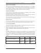
Infinity D Power System Installation Guide: -48V Plants H2007001 UL Ratings as reflected in the UL Report in May 2009. Please note the available rectifier output is reduced from the nameplate rating when converters are introduced to the system.
Infinity D Power System Installation Guide: -48V Plants H2007001 DC DISTRIBUTION PANEL OVERCURRENT-PROTECTION DEVICE CONFIGURATIONS Shelf(+) Maximum Amps(++),(+++) Manufacturer Airpax J2007002 400 charge 500 discharge Circuit Breakers Series Rating(+++++) 3-70A 1-pole 100A 2-pole LMLK, LMLHPK 150A 2-pole 250A 3-pole Comments Cumulative adjacent circuit breaker ratings cannot exceed 250A. QSGMT6 6 fuse holders – 57.
Infinity D Power System Installation Guide: -48V Plants H2007001 4. Installation Preparation Safety Please review all safety warnings in Section 3 before beginning the installation process. Observe all warnings and labels on the equipment. WARNING: Due to the possibility of working on energized circuits during these procedures, all tools and test equipment must be insulated in an approved manner. Proper ESD protection is required in order to prevent ESD damage to the equipment.
Infinity D Power System Installation Guide: -48V Plants H2007001 Packaging • • All packages should be opened with a box cutter with the blade minimally exposed so that only the sealing tape is cut. Save all packaging material until the system has been powered up and all parts are operating within specifications. Installation Tools You will need the following tools to install and test the Infinity D.
Infinity D Power System Installation Guide: -48V Plants H2007001 Anchor the Frame Floor Mounted Frames Mount the selected frame securely to the floor using floor anchors rated for the Seismic Zone of the site. We sell a floor anchor kit (847135688) with 4 Hilti 12mm Cap bolts that may be appropriate for the frame you have selected. Step Action 1. 2. Mark floor using template, frame itself, or measurements in Appendix B if 26” frame selected. Drill anchor holes.
Infinity D Power System Installation Guide: -48V Plants H2007001 Install Batteries WARNING: All batteries contain hazardous electrical energy. Lead-acid batteries contain sulfuric acid and explosive hydrogen gas. Follow all precautions noted in the literature accompanying the batteries. Use only insulated tools. CAUTION: Equipment frame anchoring, load rating, and seismic zone rating should be verified before field installing trays and batteries. Installing External Batteries Step 1. 2. 3. 4.
Infinity D Power System Installation Guide: -48V Plants H2007001 Mount the Subframe System to the Frame or Cabinet The Infinity D is provided in integrated Subframes. Each Subframe contains one Battery Connection Module, one Pulsar Controller and one or more Rectifier System Modules. Converter System Modules are not required to have a valid system and are typically on the bottom of the power equipment stack in any given Subframe. Step 1 below shows the elements included in the smallest valid Subframe.
Infinity D Power System Installation Guide: -48V Plants H2007001 Wire the Subframe Identify Areas for Each Type of Wiring The Infinity D is designed for overhead wiring. Step 1. Action Look at the framework from the top. CO Ground (RTN) DC Distribution Location for 1” AC Conduit Drop Battery Hot Terminations TOP VIEW Alarm & Control [secured near door hinge] Battery Return Terminations Infinity D Framework – Top View 2.
Infinity D Power System Installation Guide: -48V Plants H2007001 Connect ac Utility Circled below is the part of the Block Diagram to be wired first. Issue 2.
Infinity D Power System Installation Guide: -48V Plants H2007001 WARNING: Disconnect all ac branch circuits prior to making ac connections to the system. When connecting to utility source, ensure compliance to all local and national wiring rules. There are only 2 options for AC wiring: Four 20A AC circuit breakers per shelf or two 40A AC circuit breakers per shelf .If you have 4 AC circuit breaker per shelf, one for each of the rectifier positions, start at step 1 here.
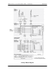
Infinity D Power System Installation Guide: -48V Plants Step Action Yes, insert each wire into the bottom of the terminal block according to these diagrams: R1 R2 R3 R4 L1 L2 L2 L3 L3 L1 L1 L2 200-240Vac Wiring Diagram for 3 Wire +PE R1 L1 N R2 L2 N R3 L3 N R4 L1 N 200-240Vac Wiring Diagram for 3 Wire + neutral +PE [NON-US ONLY] R1 L1 L2 R2 L1 L2 R3 L1 L2 R4 L1 L2 200-240Vac Wiring Diagram for 2 Wire + PE 10. 11. 12. 13. 14.
Infinity D Power System Installation Guide: -48V Plants H2007001 If you have one AC circuit breaker for each pair of rectifiers, start here. Step 1. Action Loosen the screws that secure the AC wiring cover. Loosen Screws 2. 3. 4. 5. 6. Remove the AC wiring cover. Remove the conduit knockout. At the AC service panel install a 40A double pole circuit breaker for each pair of rectifiers. Use 8 AWG wire.
Infinity D Power System Installation Guide: -48V Plants Step H2007001 Action 9. Insert the provided jumpers in the 4 locations where the dividers were removed. 10. 11. Torque each of the 8 jumper retention screws to 10 inch·lbs or 1.1 N·m. Insert each feed wire into the bottom of the terminal block according to this diagram.
Infinity D Power System Installation Guide: -48V Plants H2007001 This page intentionally left balnk. Issue 2.
Infinity D Power System Installation Guide: -48V Plants H2007001 Wire the Battery Connection Module Circled below is the part of the Block Diagram to be wired next. Issue 2.
Infinity D Power System Installation Guide: -48V Plants H2007001 Connect Central Office Ground (COG) Step 1. Locate CO Ground Termination Busbar for DC Return. Action CO Return Ground Termination Busbar Note: Landings are compatible with lugs with 1” hole spacing for 3/8” hardware. 2. Secure Central Office Ground connection.
Infinity D Power System Installation Guide: -48V Plants H2007001 Connect External Battery Cables Battery Cable landings are located at the top of the frame. The return is on your right and the hot or -48V side is on your left. The extra plastic insulators around the battery bus bars on the left confirm that this is the electrically hot side with respect to earth. Step 1. Action Loosen the four screws that secure the Battery Hot Termination cover located on the left side of the Battery Connection Module.
Infinity D Power System Installation Guide: -48V Plants Step 3. H2007001 Action Secure the Hot Lead for each battery string, starting from the middle of the bay and working to the outside. Use a double hole lug with holes on 1 inch centers. Hardware list for each termination is: (2) 801273129 3/8-16 x 1in bolt (2) 801829607 3/8-inch lockwasher (2) 802841635 3/8-inch flatwasher 4. 5. 6. 7. If required by local code or practice, treat with an oxidation inhibitor such as NO-OX.
Infinity D Power System Installation Guide: -48V Plants Step H2007001 Action 8. Lift off the Return Termination Cover to reveal the Battery Return lead termination bus bar. 9. Secure the Return Lead for each battery string. Use the back bus bar, starting toward the middle of the bay and working to the outside. Use a double hole lug with holes on 1 inch centers.
Infinity D Power System Installation Guide: -48V Plants Step 12. H2007001 Action Re-torque screws to ~6 in·lbs ( 0.5 Nm) Battery Connection Module (terminated with 1 representative battery string) Issue 2.
Infinity D Power System Installation Guide: -48V Plants H2007001 Wire -48V DC Loads Circled below is the -48V Load Wiring part of the Block Diagram wired next. Issue 2.
Infinity D Power System Installation Guide: -48V Plants H2007001 Install dc Bullet Style Circuit Breaker Modules for -48V Loads This plant makes use of a [circuit breaker]/[lug landing] assembly for each normal format bullet style circuit breaker. This section illustrates how these are installed. CAUTION: Ensure Circuit Breakers are in the OFF position prior to installation.
Infinity D Power System Installation Guide: -48V Plants Step H2007001 Action 3. Insert a Circuit Breaker Termination module starting in the lowest position: 4. Torque to 4 in lbs: Issue 2.
Infinity D Power System Installation Guide: -48V Plants Step H2007001 Action 5. Plug in Circuit Breaker: 6. 7. 8. Mark the label to the left of the circuit breaker according to standard practice in your network. Feed a wire pair from the top of the bay down to the desired location. Locate and dress the pair to tie bars in the right back corner of the DC wiring area: 9. 10. Terminate the feeding lead on the circuit breaker lug landing using the hardware provided.
Infinity D Power System Installation Guide: -48V Plants Step 11. H2007001 Action Torque all fasteners to 65 in lbs (7 Nm) using an insulated extension at least 5 inches long. Two-Pole and Three-Pole Breakers: 12. 13. 14. 15. 16. 17. 18. 19. 20. Secure Two-Pole and Three-Pole Circuit Breaker and Lug Landing Assemblies in the same fashion. Mark the label to the left of the circuit breaker according to standard practice in your network. Feed a wire pair from the top of the bay down to the desired location.
Infinity D Power System Installation Guide: -48V Plants H2007001 This page intentionally left blank. Issue 2.
Infinity D Power System Installation Guide: -48V Plants H2007001 Wire +24V DC Loads Circled below is the +24V Load Wiring part of the Block Diagram wired next. Issue 2.
Infinity D Power System Installation Guide: -48V Plants H2007001 Install dc Bullet Style Circuit Breaker Modules for +24V Loads This plant makes use of a [circuit breaker]/[lug landing] assembly for each normal format bullet style circuit breaker. This section illustrates how these are installed. CAUTION: Ensure Circuit Breakers are in the OFF position prior to installation.
Infinity D Power System Installation Guide: -48V Plants Step H2007001 Action 3. Insert a Circuit Breaker Termination module starting in the lowest position: 4. Torque to 4 in lbs: Issue 2.
Infinity D Power System Installation Guide: -48V Plants Step H2007001 Action 5. Plug in Circuit Breaker: 6. 7. 8. Mark the label to the left of the circuit breaker according to standard practice in your network. Feed a wire pair from the top of the bay down to the desired location. Locate and dress the pair to tie bars in the right back corner of the DC wiring area: Secure DC Pairs Securely to Tie Bars 9. 10. 11. Terminate the send on the circuit breaker lug landing using the hardware provided.
Infinity D Power System Installation Guide: -48V Plants Step H2007001 Action Two-Pole and Three-Pole Breakers: 12. 13. 14. 15. 16. 17. 18. 19. 20. Secure Two-Pole and Three-Pole Circuit Breaker and Lug Landing Assemblies in the same fashion. Mark the label to the left of the circuit breaker according to standard practice in your network. Feed a wire pair from the top of the bay down to the desired location. Locate and dress the pair to tie bars in the right back corner of the DC wiring area.
Infinity D Power System Installation Guide: -48V Plants H2007001 This page intentionally left blank. Issue 2.
Infinity D Power System Installation Guide: -48V Plants H2007001 Wire Loads served by GMT Type Fuses Step Action 1. Open the Converter or Rectifier System Module door 2. Locate Circuit Breaker (CB) mounting panel. 3. Install a 6 position GMT type fuse holder in 2 Circuit Breaker distribution positions (see picture) 4. Terminate the return busbar according to the instructions provided with the GMT fuse holder kit. Return Termination points 5.
Infinity D Power System Installation Guide: -48V Plants H2007001 Verify Previous Installation Steps Perform the following verification checklist after installation of batteries and wiring: Step Action 1. 2. 3. 4. 5. 6. 7. 8. 9. 10. 11. 12. 13. 14. 15. Verify cabinet is properly grounded (using Digital Multimeter (DMM)). Verify the ac equipment ground is properly connected. Verify the correct ground cable gauge is used. Use the standard grounding principles for your office.
Infinity D Power System Installation Guide: -48V Plants H2007001 Install Rectifiers and Converters Circled here are the Rectifier and Converter Installation parts of the Block Diagram. Issue 2.
Infinity D Power System Installation Guide: -48V Plants H2007001 Rectifier/Converter Installation Procedure Step Action 1. Slide the rectifier/converter partially into a slot. 2. Open the faceplate by sliding the black latch to the left to release the faceplate. 3. Push the unit firmly into the shelf until seated. Using optional air filter? Yes – Proceed to Step 4. No – Go to Step 5. Install an air filter by placing it inside the faceplate.
Infinity D Power System Installation Guide: -48V Plants H2007001 Use the above rectifier installation procedure as needed in the following steps. Note: You will be directed to use the Menu commands from the front of the Pulsar Controller. Step Action 1. Turn on ac service circuit breakers to apply power to the system rectifier positions. 2. Install a rectifier in an available rectifier position. 3.
Infinity D Power System Installation Guide: -48V Plants H2007001 This page intentionally left blank. Issue 2.
Infinity D Power System Installation Guide: -48V Plants H2007001 Install Battery Instrumentation Circled here are the Battery Instrumentation Installation parts of the Block Diagram. Issue 2.
Infinity D Power System Installation Guide: -48V Plants H2007001 This page intentionally left blank. Issue 2.
Infinity D Power System Installation Guide: -48V Plants H2007001 Install Battery VT Probes Install Battery VT Probes without Voltage Monitoring The QS873A weatherized VT-Probe is provided with 2-pin and 3-pin receptacles and a 1/4-inch ring terminal. VT-Probe Connections to Controller Connection (Lead Acid) Step Action 1. Insert the RJ-45 end of the 848719795 wireset into the Temp Connector on the controller. Open door by pressing here 2. Using voltage monitoring? Yes – Proceed to Step 2.
Infinity D Power System Installation Guide: -48V Plants Step H2007001 Action 3. Insert the 3-pin connector end into the receptacle on the closest VTProbe. 4. 5. Snap the cover closed on the VT-probe. Place the first probe to the battery post (as in the picture in Step 3). Note: Probes are typically installed one per string, located in the center of the string. Verify the number of probes (1) registered with the controller with command: MENU > STATUS > BATTERIES > TEMP PROBES PRESENT.
Infinity D Power System Installation Guide: -48V Plants H2007001 VT-Probe/Battery Voltage Monitor Connections to Controller (Optional) Step 1. 2. 3. 4. 5. 6. Action Insert one RJ-45 end of the 848652947 wireset into the J2 Connector on the controller and the other end to the first ES771A Remote Voltage Monitor module. Set address switch to 01. Verify the number of modules (1) registered with the controller with command: MENU > STATUS > BATTERIES > NUM MIDPT MODULES.
Infinity D Power System Installation Guide: -48V Plants Step H2007001 Action Are the LEDs on the module(s) on (and not red) and are the number of registered modules the same as the number used? Yes – Go to Step 9. No – Proceed to Step 7. 7. 8. Check integrity of all cable connections. Issue the Clear Events command: MENU > CONTROL / OPERATIONS > CLEAR EVENTS. 9. (If the LEDs are still not lit green or if the number of registered modules still does not agree, call your local field representative.
Infinity D Power System Installation Guide: -48V Plants H2007001 Setup Pulsar Controller Circled below is the controller part of the block diagram. Input & Output Office alarms are wired to the controller by the customer as are LAN and Temperature Compensation probes. Issue 2.
Infinity D Power System Installation Guide: -48V Plants H2007001 Install Controller Field Wiring In addition to the temperature instrumentation, the controller has field connections for Alarm Inputs, Alarm Outputs and a Local Area Network (LAN). Step Action 1. Insert the terminated end of the Alarm Input wireset (CC848817651) into the Input Alarms connector on the top edge of the controller. 2.
Infinity D Power System Installation Guide: -48V Plants H2007001 Change LAN to Server Mode To access the controller directly from a PC, you must first change LAN connection to server mode. Step 1. 2. 3. 4. 5. 6. 7. 8. 9. 10. Action Press Menu or Accept key, ■. Press down arrow, ▼, to Configuration. Press the right arrow key, ► (or square “accept” key, ■) to advance. Press down arrow, ▼, to Communications Ports. Press the right arrow key, ► (or square “accept” key, ■) to advance.
Infinity D Power System Installation Guide: -48V Plants H2007001 Restore the LAN Connection to Client Mode As good policy, always leave the controller in Client mode. Step 1. 2. 3. 4. 5. 6. 7. 8. 9. 10. Action Press Menu or Accept key, ■. Press down arrow, ▼, to Configuration. Press the right arrow key, ► (or square “accept” key, ■) to advance. Press down arrow, ▼, to Communications Ports. Press the right arrow key, ► (or square “accept” key, ■) to advance. Press down arrow, ▼, to Network Settings.
Infinity D Power System Installation Guide: -48V Plants H2007001 Acceptance Testing NOTE: The controller may report a limited recharge alarm during these tests. NOTE: At any time you encounter difficulty with these steps, refer to the Troubleshooting Section. Communication with Rectifiers and Converters Step Action 1. Place external battery disconnect switches in the ON (connected) position if equipped. 2. Turn on all ac circuit breakers supplying rectifiers.
Infinity D Power System Installation Guide: -48V Plants H2007001 Miscellaneous Alarms (Batteries must be connected) Distribution Alarms Step 1. 2. 3. Action Manually connect a piece of wire from the circuit breaker feed bus to the distribution alarm strip. Verify an FAJ – Fuse Alarm Major is reported by the controller. Remove the wire. Verify the alarm clears. Repeat test for each distribution panel or sub-system. ac Fail Alarms Step 1. 2. 3. 4. 5. 6.
Infinity D Power System Installation Guide: -48V Plants H2007001 Manual Contactor Control and Alarms WARNING: If this is an operating plant with loads, skip this test. Step 1. 2. 3. 4. Action Open the contactor by controller command (MENU > CONTROL / OPERATIONS > DISCONNECTS). Verify the controller reports a Contactor Open alarm. Close the contactor by controller command. Verify the alarms clear and the controller returns to Normal.
Infinity D Power System Installation Guide: -48V Plants H2007001 This page intentionally left blank. Issue 2.
Infinity D Power System Installation Guide: -48V Plants H2007001 5. Troubleshooting The Block Diagram below is a first step to troubleshooting an Infinity D -48V Plant. Issue 2.
Infinity D Power System Installation Guide: -48V Plants H2007001 Troubleshooting NE-Series Rectifiers/Converters The status of an NE-Series rectifier or converter is provided by LEDs on their face, and by extensive real time data, alarm and event history accessible through the system controller. Rectifier/Converter Status LEDs LEDs Condition Normal operation: No alarms, inputs and outputs are in their normal range, communicating with the system controller. Unpowered: No input or output voltage present.
Infinity D Power System Installation Guide: -48V Plants LEDs H2007001 Condition ACF [ac Fail]: Rectifier input is missing or out of range. Correct ac fault. In F [Input Fail]: Re-labeled LED on converter indicates Converter input is out of range. Correct converter input fault. Shutdown∗: The unit cannot deliver output. • High Voltage Shutdown • Thermal Shutdown • Under Voltage Protect • Component failure 1. Check rectifier or converter status on controller display to determine cause of shutdown 2.
Infinity D Power System Installation Guide: -48V Plants H2007001 Troubleshooting VT-Probes Checking for Defective VT-Probes (If a Voltage Channel Failure and/or Thermal Probe Failure alarm occurs) Step Action 1. 2. 3. 4. 5. Disconnect the first probe from its RJ-45 terminal block. Run the command: MENU > CONTROL / OPERATIONS > UNINSTALL EQUIPMENT. Is the system controller green Normal LED lit? Yes – Removed probe is defective. Replace it. No – Reinstall the removed probe. Proceed to Finished. Step 4.
Infinity D Power System Installation Guide: -48V Plants H2007001 6. Product Warranty A. Seller warrants to Customer only, that: 1. As of the date title to Products passes, Seller will have the right to sell, transfer, and assign such Products and the title conveyed by Seller shall be good; 2.
Infinity D Power System Installation Guide: -48V Plants D. E. F. G. H2007001 whether or not installed by Seller, Seller at its option, may repair the cable and Wire Products at Customer’s site. If Seller has elected to repair or replace a defective Product, Customer shall have the option of removing and reinstalling or having Seller remove and reinstall the defective or nonconforming Product. The cost of the removal and the reinstallation shall be borne by Customer.
Infinity D Power System Installation Guide: -48V Plants H2007001 Appendix A: Pulsar Controller User Interface Overview The Galaxy Pulsar Plus NE843 family of controllers monitor and control system components including rectifiers, converters, and distribution modules via a multi-drop RS485 digital communications bus. System status, parameters, settings, and alarm thresholds can be viewed and configured from the controller’s front panel display.
Infinity D Power System Installation Guide: -48V Plants H2007001 Menu Navigation Buttons The NE843 has six tactile buttons to use to navigate through a structured menu system. The buttons serve multiple purposes depending on the screen a user is at. These functions are summarized below. Buttons Description Display Contrast Parameter Change Direction Buttons Enter Button ESC Button In the Main Display, the ▲▼ buttons increase or decrease the display contrast.
Infinity D Power System Installation Guide: -48V Plants H2007001 NE843 Status LEDs The Pulsar Plus NE843 controller family provides three separate LED indicators to help assist in providing more specific indications of the system status. These LEDs provide are used to provide specific indication concerning the AC and DC system status as well as a separate indicator for a Battery on Discharge state. These LEDs have factory assigned defaults as indicated in the table below.
Infinity D Power System Installation Guide: -48V Plants H2007001 Once the audible cut-off is selected the alarms present in the system are listed. An indicator on the default front panel screen is provided to inform that the audible alarm cutoff is active. The audible alarm can also be turned-back on following similar procedures. The audible alarm may be disabled altogether through proper configuration at the front panel or through remote means.
Infinity D Power System Installation Guide: -48V Plants Port Front Panel J7 H2007001 Description A laptop PC can be connected to standard DB9 connector J7 to provide a ground-referenced RS-232 serial connection using EasyView for local access. The port can also be configured to be used with an external modem. A position (as shown below) is reserved for a second RJ45 Ethernet connection in the future. It is covered for now.
Infinity D Power System Installation Guide: -48V Plants H2007001 Access to the main menu starts at the default front panel screen shown below. The front panel default screen displays the primary and secondary (if present) bus voltages along with their respective total load in two different fonts. Front Panel Default Menu Test Jack Reference Plant Voltage (Rectifier) Plant Current (Load) Plant Current (Converter) Plant Voltage (Converter) Alarms The operating mode of the system is also displayed.
Infinity D Power System Installation Guide: -48V Plants H2007001 The up, down, left and right arrows are used to enter the appropriate password. Upon entering a correct PIN the following momentary screen shows up and then disappears leaving the user at the menu location prior to entering the PIN. A user must enter the PIN for items that generally are not deemed as functions of a typical maintenance routine.
Infinity D Power System Installation Guide: -48V Plants 9. 10. 11. 12. 13. 14. 15. 16.
Infinity D Power System Installation Guide: -48V Plants H2007001 . Figure 5-3: Status Menu Issue 2.
Infinity D Power System Installation Guide: -48V Plants H2007001 Figure 5-4: Control / Operations and History Menus Issue 2.
Infinity D Power System Installation Guide: -48V Plants H2007001 Figure 5-5: Configuration Menu (part 1) Issue 2.
Infinity D Power System Installation Guide: -48V Plants H2007001 Figure 5-6: Configuration Menu (part 2) Issue 2.
Infinity D Power System Installation Guide: -48V Plants H2007001 Appendix B: Reference Information Pulsar Controller Field Wiring Connector Definitions One-Wire Battery Peripheral Connector Temp is a standard shielded RJ-45 receptacle provided for making connections to one-wire QS873 VT-Probes and or to the ES771A Remote Mid-string Voltage Monitor.
Infinity D Power System Installation Guide: -48V Plants H2007001 Pin # (Wire Color) 1 (BL) 2 (O) 3 (G) 4 (BR) 5 (S) 6 (BL) 7 (O) 8 (G) 9 (BR) 10 (S) Signal Name Twisted Pair Office Alarm Connector All standard controller output alarm connections are available from the output connector. Connector J4 provides access to the primary customer alarm output interface. Connector J4 is a 20-pin right angle header with latching capability. Standard color coded cable assemblies are available.
Infinity D Power System Installation Guide: -48V Plants H2007001 Reference Information for 26 inch Frame (all dimensions in inches) Issue 2.
Infinity D Power System Installation Guide: -48V Plants H2007001 Revision History Issue 2.0 June 3, 2009 – Added Safety section updates; Specified 20A and 40A circuit breakers in AC wiring section; changed colors of AC wires from white to black to avoid confusion; indicated that alarm wire set conductors are paired; added passwords for LAN access. Corrected trouble shooting diagram. Issue 1.0 October 3, 2008 – Initial release. Issue 2.