
Owner manual
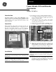
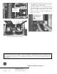

Figure 3. Plastic button installed on the breaker mechanism.
Figure 4. Removing the original On button from the breaker cover by
pressing the locking tabs with two screwdrivers.
6. Slide the replacement On button into the slot on the front
of the breaker cover, as shown in Figure 5, then press it
in until the locking tabs click into place.
7. Reinstall the breaker top cover, ensuring that the Trip
Unit and aluminum accessory sleeve are properly aligned
with the cover. Tighten the four #10-32 screws to 15 in-
lb.
8. Replace the trim plate, if installed, and tighten the four
#8-32 screws to 15 in-lb.
Figure 5. Installing the replacement On button into the breaker cover.
These instructions do not cover all details or variations in e
q
ui
p
ment nor do the
y
p
rovide for ever
y
p
ossible contin
g
enc
y
that
ma
y
be met in connection with installation, o
p
eration, or maintenance. Should further information be desired or should
p
articular
p
roblems arise that are not covered sufficientl
y
for the
p
urchaser’s
p
ur
p
oses, the matter should be referred to the
GE Company.
g
GE Electrical Distribution & Control
General Electric Company
41 Woodford Ave., Plainville, CT 06062
DEH– 025A 0997 © 1997 General Electric Company
Plastic Button
Installed on
Mechanism