
Instruction Manual
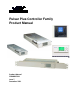


Pulsar Plus Controller Family
Issue 7 December 2011 6
Table of Tables
Table 1 Pulsar Plus Controller Family Product Options .............................................................................. 16
Table 2 Controller Standard Defaults Door Mounted ................................................................................ 21
Table 3 Table 2 Controller Standard Defaults NE843G .............................................................................. 27
Table 4 Auxiliary Input Connector .............................................................................................................. 32
Table 5 Output Alarm Connector ............................................................................................................... 34
Table 6 Local RS-232 Serial Port Signals ..................................................................................................... 37
Table 7 Power And Sense Connector ......................................................................................................... 38
Table 8 Status LEDs - Pulsar ........................................................................................................................ 56
Table 9 Status LEDs - Dedicated - Phoenix ................................................................................................. 58
Table 10 Status LEDs - Custom Assignable - Phoenix ................................................................................. 58
Table 11 Rectifier Status ............................................................................................................................. 70
Table 12 Converter Status .......................................................................................................................... 70
Table 13 Batteries Status ............................................................................................................................ 71
Table 14 Shunt Currents Status .................................................................................................................. 71
Table 15 Disconnect States Status .............................................................................................................. 71
Table 16 Alarm Thresholds Status .............................................................................................................. 72
Table 17 Enabled/Disabled Info Status ...................................................................................................... 72
Table 18 Network Settings Status .............................................................................................................. 73
Table 19 System Info Status ....................................................................................................................... 74
Table 20 Control/Operations ...................................................................................................................... 74
Table 21 History .......................................................................................................................................... 76
Table 22 Float Settings Configuration ........................................................................................................ 77
Table 23 Shunt Monitors Configuration ..................................................................................................... 78
Table 24 Shunt Type Configuration ............................................................................................................ 79
Table 25 Rectifiers Configuration ............................................................................................................... 81
Table 26 Batteries Configuration
................................................................................................................ 82
Table 27 Contactors Configuration ............................................................................................................. 84
Table 28 Disconnects Configuration ........................................................................................................... 84
Table 29 Converters Configuration ............................................................................................................ 85
Table 30 Boost Configuration ..................................................................................................................... 86
Table 31 System Settings Configuration ..................................................................................................... 88
Table 32 Communication Ports Configuration ........................................................................................... 88
Table 33 NE872 J1 Signal Description ....................................................................................................... 103
Table 34 NE872 J2 Signal Description ....................................................................................................... 104
Table 35 NE872 TB1 Signal Description .................................................................................................... 104
Table 36 NE872 J100 and J101 Signal Description ................................................................................... 105
Table 37 QS871 J1 Signal Description ....................................................................................................... 107
Table 38 QS871 J2 Signal Description ....................................................................................................... 108
Table 39 QS871 J3 Signal Description ....................................................................................................... 108
Table 40 QS871 J100 and J101 Signal Description ................................................................................... 108
Table 41 ES772 Connector J1 Pinout Definitions ..................................................................................... 112
Table 42 ES772 Connector J3 Pin Definitions ........................................................................................... 112
Table 43 Auxiliary Port Connector Signals ................................................................................................ 115
Table 44 Infinity NE System Troubleshooting .......................................................................................... 119
Table 45 Specifications ............................................................................................................................. 123
Table 46 T1.317 Power System Related Commands ................................................................................ 140
Table 47 T1.317 User Login Related commands ...................................................................................... 142