
Manual

GE
Data Sheet
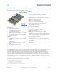
QBVW033A0B Barracuda Series; DC-DC Converter Power Modules
36-75Vdc Input; 12.0Vdc, 33.0A, 400W Output
May 21, 2013 ©2012 General Electric Company. All rights reserved. Page 10
Feature Descriptions (continued)
Thermal Considerations
The thermal data presented here is based on physical
measurements taken in a wind tunnel, using automated
thermo-couple instrumentation to monitor key component
temperatures: FETs, diodes, control ICs, magnetic cores,
ceramic capacitors, opto-isolators, and module pwb
conductors, while controlling the ambient airflow rate and
temperature. For a given airflow and ambient temperature, the
module output power is increased, until one (or more) of the
components reaches its maximum derated operating
temperature, as defined in IPC-9592B. This procedure is then
repeated for a different airflow or ambient temperature until a
family of module output derating curves is obtained.
The power modules operate in a variety of thermal
environments and sufficient cooling should be provided to help
ensure reliable operation. Thermal considerations include
ambient temperature, airflow, module power dissipation, and
the need for increased reliability. A reduction in the operating
temperature of the module will result in an increase in
reliability.
Heat-dissipating components are mounted on the top side of
the module. Heat is removed by conduction, convection and
radiation to the surrounding environment. Proper cooling can
be verified by measuring the thermal reference
temperature
(TH
1
or TH
2
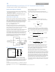
). Peak temperature occurs at the position indicated
in Figure 17 and 18. For reliable operation this temperature
should not exceed TH
1
=125°C or TH
2
=105°C. For extremely high
reliability you can limit this temperature to a lower value.
.
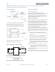
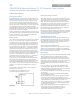
Figure 17. Location of the thermal reference temperature
TH
1
for open frame module.
Figure 18. Location of the thermal reference temperature
TH
2
for base plate module.
The output power of the module should not exceed the rated
power for the module as listed in the Ordering Information
table.
Please refer to the Application Note “Thermal Characterization
Process For Open-Frame Board-Mounted Power Modules” for a
detailed discussion of thermal aspects including maximum
device temperatures.
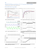
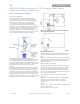
Heat Transfer via Convection
Increased airflow over the module enhances the heat transfer
via convection. The thermal derating of figure 19- 23 shows
the maximum output current that can be delivered by each
module in the indicated orientation without exceeding the
maximum TH
x
temperature versus local ambient temperature
(T
A
) for several air flow conditions.
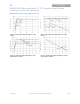
The use of Figure 19 is shown in the following example:
Example
What is the minimum airflow necessary for a QBVW033A0B
operating at V
I
= 48 V, an output current of 20A, and a
maximum ambient temperature of 60 °C in transverse
orientation.
Solution:
Given: V
in
= 48V, I
O
= 20A, T
A
= 60 °C Determine required airflow
velocity (Use Figure 19):
Velocity = 0.5m/s (100 LFM) or greater.