
Manual


GE
Data Sheet
QBVW033A0B Barracuda Series; DC-DC Converter Power Modules
36-75Vdc Input; 12.0Vdc, 33.0A, 400W Output
May 21, 2013 ©2012 General Electric Company. All rights reserved. Page 12
Layout Considerations
The QBVW033 power module series are low profile in order
to be used in fine pitch system card architectures. As such,
component clearance between the bottom of the power
module and the mounting board is limited. Avoid placing
copper areas on the outer layer directly underneath the
power module. Also avoid placing via interconnects
underneath the power module.
For additional layout guide-lines, refer to FLTR100V10 Data
Sheet.
Through-Hole Lead-Free Soldering
Information
The RoHS-compliant, Z version, through-hole products use
the SAC (Sn/Ag/Cu) Pb-free solder and RoHS-compliant
components. The module is designed to be processed
through single or dual wave soldering machines. The pins
have a RoHS-compliant, pure tin finish that is compatible
with both Pb and Pb-free wave soldering processes. A
maximum preheat rate of 3C/s is suggested. The wave
preheat process should be such that the temperature of the
power module board is kept below 210C. For Pb solder, the
recommended pot temperature is 260C, while the Pb-free
solder pot is 270C max.
Reflow Lead-Free Soldering Information
The RoHS-compliant through-hole products can be
processed with the following paste-through-hole Pb or Pb-
free reflow process.
Max. sustain temperature :
245C (J-STD-020C Table 4-2: Packaging Thickness>=2.5
mm
/ Volume > 2000
mm
3
),
Peak temperature over 245C is not suggested due to the
potential reliability risk of components under continuous
high-temperature.
Min. sustain duration above 217C : 90 seconds
Min. sustain duration above 180C : 150 seconds
Max. heat up rate: 3C/sec
Max. cool down rate: 4C/sec
In compliance with JEDEC J-STD-020C spec for 2 times
reflow requirement.
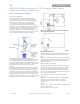
Pb-free Reflow Profile
BMP module will comply with J-STD-020 Rev. C
(Moisture/Reflow Sensitivity Classification for
Nonhermetic Solid State Surface Mount Devices) for both
Pb-free solder profiles and MSL classification
procedures. BMP will comply with JEDEC J-STD-020C
specification for 3 times reflow requirement. The suggested
Pb-free solder paste is Sn/Ag/Cu (SAC). The recommended
linear reflow profile using Sn/Ag/Cu solder is shown in Figure
24.
Figure 25. Recommended linear reflow profile using
Sn/Ag/Cu solder.
MSL Rating
The QBVW033A0B modules have a MSL rating of 2a.
Storage and Handling
The recommended storage environment and handling
procedures for moisture-sensitive surface mount packages
is detailed in J-STD-033 Rev. A (Handling, Packing, Shipping
and Use of Moisture/Reflow Sensitive Surface Mount
Devices). Moisture barrier bags (MBB) with desiccant are
required for MSL ratings of 2 or greater. These sealed
packages should not be broken until time of use. Once the
original package is broken, the floor life of the product at
conditions of 30°C and 60% relative humidity varies
according to the MSL rating (see J-STD-033A). The shelf life
for dry packed SMT packages will be a minimum of 12
months from the bag seal date, when stored at the following
conditions: < 40° C, < 90% relative humidity.
Post Solder Cleaning and Drying
Considerations
Post solder cleaning is usually the final circuit-board
assembly process prior to electrical board testing. The result
of inadequate cleaning and drying can affect both the
reliability of a power module and the testability of the
finished circuit-board assembly. For guidance on
appropriate soldering, cleaning and drying procedures, refer
to GE Board Mounted Power Modules: Soldering and
Cleaning Application Note (AN04-001).
If additional information is needed, please consult with your
GE representative for more details.