
Manual

GE
Data Sheet
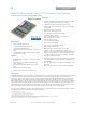
QBVW033A0B Barracuda Series; DC-DC Converter Power Modules
36-75Vdc Input; 12.0Vdc, 33.0A, 400W Output
May 21, 2013 ©2012 General Electric Company. All rights reserved. Page 4
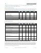
Isolation Specifications
Parameter Symbol Min Typ Max Unit
Isolation Capacitance C
iso
1000
pF
Isolation Resistance R
iso
10
MΩ
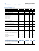
Feature Specifications
Unless otherwise indicated, specifications apply over all operating input voltage, resistive load, and temperature conditions. See
Feature Descriptions for additional information.
Parameter Device Symbol Min Typ Max Unit
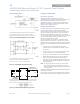
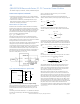
Remote On/Off Signal Interface
(V
IN
=V
IN, min
to V
IN, max
, Signal referenced to V
IN-
terminal)
Negative Logic: device code suffix “1”
Lo
g
ic Low = module On, Lo
g
ic Hi
g
h = module Off
Positive Logic: No device code suffix required
Logic Low = module Off, Logic High = module On
Logic Low Specification
On/Off Thresholds:
Remote On/Off Current – Logic Low (Vin =100V) All I
on/off
280
310 μA
Logic Low Voltage All V
on/off
-0.3
0.8 V
dc
Logic High Voltage – (Typ = Open Collector) All V
on/off
2.0
14.5 V
dc
Logic High maximum allowable leakage current
(V
on/off
= 2.0V)
All I
on/off
10 μA
Maximum voltage allowed on On/Off pin All V
on/off
14.5 V
dc
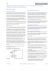
Turn-On Delay and Rise Times (I
O
=I
O, max
)
T
delay
=Time until V
O
= 10% of V
O,set
from either application of Vin
with Remote On/Off set to On (Enable with Vin); or operation of
Remote On/Off from Off to On with Vin already applied for at
least 150 milli-seconds (Enable with on/off).
* Increased T
delay
due to startup for parallel modules.
All w/o P
option
T
delay,
Enable with Vin
150 ms
All w/o P
option
T
delay, Enable with
on/off
10 ms
All w/ P
option
T
delay
,
Enable with Vin
180* ms
All w/ P
option
T
delay, Enable with
on/off
40* ms
T
rise
=Time for V
O
to rise from 10% to 90% of V
O,set
, For C
O
>5000uF, I
O
must be < 50% I
O, max
during T
rise
.
* Increased T
rise
when pre-bias Vo exists at startup for
parallel modules.
All w/o P
option
T
rise
15 ms
All w/ P
option
T
rise
300* ms
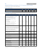
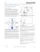
Remote Sense Range
All w/ 9
option
V
Sense
0.5 V
dc
Load Sharing Current Balance
(difference in output current across all modules with outputs in
parallel, no load to full load)
P Option
I
diff
3 A
Output Voltage Adjustment range
All w/ 9
option
V
O, set
8.1
13.2 V
dc
Output Overvoltage Protection
All w/o 9
option
V
O,limit
14.5
17.0 V
dc
All w/ 9
option
V
O,limit
V
O,set
+2.5V
V
O,set
+5.0V V
dc
Overtemperature Protection
All T
ref
140
°C
(See Feature Descriptions)
Input Undervoltage Lockout
Turn-on Threshold (Default)
33 35 36 V
dc
Turn-off Threshold (Default)
31 33 34 V
dc
Input Overvoltage Lockout
Turn-off Threshold (Default)
86
V
dc
Turn-on Threshold (Default)
76 79
V
dc