
Manual

GE
Data Sheet
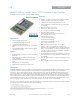
QBVW033A0B Barracuda Series; DC-DC Converter Power Modules
36-75Vdc Input; 12.0Vdc, 33.0A, 400W Output
May 21, 2013 ©2012 General Electric Company. All rights reserved. Page 7
Test Configurations
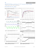
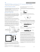
Note: Measure input reflected-ripple current with a simulated
source inductance (LTEST) of 12 µH. Capacitor CS offsets
possible battery impedance. Measure current as shown above.
Figure 11. Input Reflected Ripple Current Test Setup.
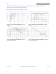
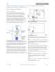
Note: Use a 1.0 µF ceramic capacitor and a 10 µF aluminum or
tantalum capacitor. Scope measurement should be made
using a BNC socket. Position the load between
51 mm and 76 mm (2 in. and 3 in.) from the module.
Figure 12. Output Ripple and Noise Test Setup.
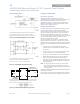
Note: All measurements are taken at the module terminals. When
socketing, place Kelvin connections at module terminals to avoid
measurement errors due to socket contact resistance.
Figure 13. Output Voltage and Efficiency Test Setup.
Design Considerations
Input Source Impedance
The power module should be connected to a low
ac-impedance source. Highly inductive source impedance can
affect the stability of the power module. For the test
configuration in Figure 11, a 100μF electrolytic capacitor, C
in
,
(ESR<0.7 at 100kHz), mounted close to the power module
helps ensure the stability of the unit.
Safety Considerations
For safety-agency approval of the system in which the power
module is used, the power module must be installed in
compliance with the spacing and separation requirements of
the end-use safety agency standard, i.e., ANSI/ UL* 60950-1-
2011 Recognized, CAN/CSA
†
C22.2 No.60950-1-07, Second
Edition + A1:2011 (MOD) Certified IEC 60950-1:2005 (2nd edition)
+ A1:2009 and EN 60950-1:2006 + A11:2009 + A1:2010 +
A12:2011, and VDE‡ 0805-1 Licensed
If the input source is non-SELV (ELV or a hazardous voltage
greater than 60 Vdc and less than or equal to 75Vdc), for the
module’s output to be considered as meeting the requirements
for safety extra-low voltage (SELV), all of the following must be
true:
The input source is to be provided with reinforced
insulation from any other hazardous voltages, including
the ac mains.
One V
IN
pin and one V
OUT
pin are to be grounded, or both
the input and output pins are to be kept floating.
The input pins of the module are not operator accessible.
Another SELV reliability test is conducted on the whole
system (combination of supply source and subject
module), as required by the safety agencies, to verify that
under a single fault, hazardous voltages do not appear at
the module’s output.
Note: Do not ground either of the input pins of the module
without grounding one of the output pins. This may
allow a non-SELV voltage to appear between the output
pins and ground.
The power module has safety extra-low voltage (SELV) outputs
when all inputs are SELV.
The input to these units is to be provided with a maximum 30 A
fast-acting (or time-delay) fuse in the ungrounded input lead.
LOAD
CONTACT AND
SUPPLY
I
I
CONTACT
V
I
(+)
V
I
(–)
V
O1
DISTRIBUTION LOSSES
RESISTANCE
I
O
V
O2