
Manual

GE
Data Sheet
QBVW033A0B Barracuda Series; DC-DC Converter Power Modules
36-75Vdc Input; 12.0Vdc, 33.0A, 400W Output
May 21, 2013 ©2012 General Electric Company. All rights reserved. Page 8
Feature Descriptions
Overcurrent Protection
To provide protection in a fault output overload condition, the
module is equipped with internal current-limiting circuitry and
can endure current limiting continuously. If the overcurrent
condition causes the output voltage to fall greater than 4.0V
from V
o,set
, the module will shut down and remain latched off.
The overcurrent latch is reset by either cycling the input power
or by toggling the on/off pin for one second. If the output
overload condition still exists when the module restarts, it will
shut down again. This operation will continue indefinitely until
the overcurrent condition is corrected.
A factory configured auto-restart option (with overcurrent and
overvoltage auto-restart managed as a group) is also available.
An auto-restart feature continually attempts to restore the
operation until fault condition is cleared.
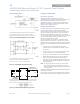
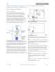
Remote On/Off
The module contains a standard on/off control circuit reference
to the V
IN
(-) terminal. Two factory configured remote on/off
logic options are available. Positive logic remote on/off turns
the module on during a logic-high voltage on the ON/OFF pin,
and off during a logic low. Negative logic remote on/off turns
the module off during a logic high, and on during a logic low.
Negative logic, device code suffix "1," is the factory-preferred
configuration. The On/Off circuit is powered from an internal
bias supply, derived from the input voltage terminals. To turn
the power module on and off, the user must supply a switch to
control the voltage between the On/Off terminal and the V
IN
(-)
terminal (V
on/off
). The switch can be an open collector or
equivalent (see Figure 14). A logic low is V
on/off
= -0.3V to 0.8V.
The typical I
on/off
during a logic low (Vin=48V, On/Off
Terminal=0.3V) is 147µA. The switch should maintain a logic-
low voltage while sinking 310µA. During a logic high, the
maximum V
on/off
generated by the power module is 8.2V. The
maximum allowable leakage current of the switch at V
on/off
=
2.0V is 10µA. If using an external voltage source, the maximum
voltage V
on/off
on the pin is 14.5V with respect to the V
IN
(-)
terminal.
If not using the remote on/off feature, perform one of the
following to turn the unit on:
For negative logic, short ON/OFF pin to V
IN
(-).
For positive logic: leave ON/OFF pin open.
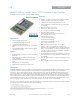
Figure 14. Remote On/Off Implementation.
Output Overvoltage Protection
The module contains circuitry to detect and respond to output
overvoltage conditions. If the overvoltage condition causes the
output voltage to rise above the limit in the Specifications
Table, the module will shut down and remain latched off. The
overvoltage latch is reset by either cycling the input power, or
by toggling the on/off pin for one second. If the output
overvoltage condition still exists when the module restarts, it
will shut down again. This operation will continue indefinitely
until the overvoltage condition is corrected.
A factory configured auto-restart option (with overcurrent and
overvoltage auto-restart managed as a group) is also available.
An auto-restart feature continually attempts to restore the
operation until fault condition is cleared.
Overtemperature Protection
These modules feature an overtemperature protection circuit
to safeguard against thermal damage. The circuit shuts down
the module when the maximum device reference temperature
is exceeded. The module will automatically restart once the
reference temperature cools by ~25°C.
Input Under/Over voltage Lockout
At input voltages above or below the input under/over voltage
lockout limits, module operation is disabled. The module will
begin to operate when the input voltage level changes to within
the under and overvoltage lockout limits.
Load Sharing
For higher power requirements, the QBVW033A0 power module
offers an optional feature for parallel operation (-P Option
code). This feature provides a precise forced output voltage
load regulation droop characteristic. The output set point and
droop slope are factory calibrated to insure optimum matching
of multiple modules’ load regulation characteristics. To
implement load sharing, the following requirements should be
followed:
The V
OUT
(+) and V
OUT
(-) pins of all parallel modules must be
connected together. Balance the trace resistance for each
module’s path to the output power planes, to insure best load
sharing and operating temperature balance.
V
IN
must remain between 40V
dc
and 75V
dc
for droop sharing to
be functional.
It is permissible to use a common Remote On/Off signal to
start all modules in parallel.
These modules contain means to block reverse current flow
upon start-up, when output voltage is present from other
parallel modules, thus eliminating the requirement for external
output ORing devices. Modules with the –P option may
automatically increase the Turn On delay, T
delay
, as specified in
the Feature Specifications Table, if output voltage is present
on the output bus at startup.
When parallel modules startup into a pre-biased output, e.g.
partially discharged output capacitance, the T
rise
is
automatically increased, as specified in the Feature
Specifications Table, to insure graceful startup.