
Manual

GE
Data Sheet
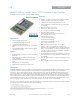
QBVW033A0B Barracuda Series; DC-DC Converter Power Modules
36-75Vdc Input; 12.0Vdc, 33.0A, 400W Output
May 21, 2013 ©2012 General Electric Company. All rights reserved. Page 9
Feature Descriptions (continued)
Insure that the total load is <50% I
O,MAX
(for a single module)
until all parallel modules have started (load full start > module
T
delay
time max + T
rise
time).
If fault tolerance is desired in parallel applications, output
ORing devices should be used to prevent a single module
failure from collapsing the load bus.
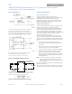
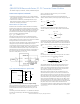
Remote Sense (“9” Option Code)
Remote sense minimizes the effects of distribution losses by
regulating the voltage at the remote-sense connections (See
Figure 15). The SENSE(-) pin should be always connected to V
O
(–
).The voltage between the remote-sense pins and the output
terminals must not exceed the output voltage sense range
given in the Feature Specifications table:
[V
O
(+) – V
O
(–)] – [SENSE(+) ] 0.5 V
Although the output voltage can be increased by both the
remote sense and by the trim, the maximum increase for the
output voltage is not the sum of both. The maximum increase is
the larger of either the remote sense or the trim.
The amount of power delivered by the module is defined as the
voltage at the output terminals multiplied by the output
current. When using remote sense and trim, the output voltage
of the module can be increased, which at the same output
current would increase the power output of the module. Care
should be taken to ensure that the maximum output power of
the module remains at or below the maximum rated power
(Maximum rated power = V
o,set
x I
o,max
).
Figure 15. Circuit Configuration for remote sense.
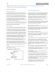
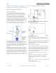
Trim, Output Voltage Adjust (“9” Option Code)
V
O
(+)
TRIM
V
O
(-)
R
trim-down
LOAD
QBVW033A0
R
trim-up
Figure 16. Circuit Configuration to Trim Output Voltage.
Trimming allows the output voltage set point to be increased or
decreased; this is accomplished by connecting an external
resistor between the TRIM pin and either the V
O
(+) pin or the
V
O
(-) pin.
Connecting an external resistor (R
trim-down
) between the TRIM pin
and the Vo(-) (or Sense(-)) pin decreases the output voltage set
point. To maintain set point accuracy, the trim resistor
tolerance should be ±1.0%.
The following equation determines the required external
resistor value to obtain a percentage output voltage change of
∆%:
22.10
%
511
downtrim
R
Where
100%
,
,
seto
desiredseto
V
VV
For example, to trim-down the output voltage of the 12V
nominal module by 20% to 9.6V, Rtrim-down is calculated as
follows:
20%
22.10
20
511
downtrim
R
kR
downtrim
3.15
Connecting an external resistor (R
trim-up
) between the TRIM pin
and the V
O
(+) (or Sense (+)) pin increases the output voltage set
point. The following equations determine the required external
resistor value to obtain a percentage output voltage change of
∆%:
22.10
%
511
%225.1
%)100(11.5
,seto
uptrim
V
R
Where
100%
,
,
seto
setodesired
V
VV
For example, to trim-up the output voltage of the 12V module
by 5% to 12.6V, R
trim-up
is calculated is as follows:
5%
22.10
5
511
5225.1
)5100(0.1211.5
uptrim
R
8.938
uptrim
R
The voltage between the Vo(+) and Vo(–) terminals must not
exceed the minimum output overvoltage protection value
shown in the Feature Specifications table. This limit includes
any increase in voltage due to remote-sense compensation
and output voltage set-point adjustment trim.
Although the output voltage can be increased by both the
remote sense and by the trim, the maximum increase for the
output voltage is not the sum of both. The maximum increase is
the larger of either the remote sense or the trim. The amount of
power delivered by the module is defined as the voltage at the
output terminals multiplied by the output current. When using
remote sense and trim, the output voltage of the module can
be increased, which at the same output current would increase
the power output of the module. Care should be taken to
ensure that the maximum output power of the module remains
at or below the maximum rated power (Maximum rated power
= V
O,set
x I
O,max
).