SGT5000_050-080_UPS_GE_01 GE Digital Energy Power Quality Installation Guide Uninterruptible Power supply Digital Energy™ SG Series 50 & 80 kVA 480 VAC UL / Series 0 Manufactured by: GE Consumer & Industrial SA General Electric Company CH – 6595 Riazzino (Locarno) Switzerland T +41 (0)91 / 850 51 51 F +41 (0)91 / 850 51 44 www.gedigitalenergy.
Model: SG Series 50 & 80 kVA / Series 0 Issue by Product Document Department – Riazzino - CH Date of issue: 01/30/2006 File name: OPM_SGT_ISG_50K_80K_0US_V040 Revision: 4.0 Identification No.: Up-dating Revision Concerns Date 2.0 Modified Section 3.8.3 – Power connection dual input utility 08/25/2004 3.0 House-style GE Consumer & Industrial 01/30/2006 4.
Dear Customer, We thank you for selecting our products and are pleased to count you amongst our very valued customers at GE. We trust that the use of the SG Series Uninterruptible Power Supply system, developed and produced to the highest standards of quality, will give you complete satisfaction. Please read carefully the Installation Guide, which contains all the necessary information and describes all you need to know about the use of the UPS.
Preface Congratulations on your choice of a SG Series Uninterruptible Power Supply (UPS). It will help eliminate load disturbances due to unexpected power problem. This manual describes how to prepare the installation site, and it provides weight and dimensions and procedures for moving, installing and connecting the UPS.
Table of contents Page 1 IMPORTANT SAFETY INSTRUCTIONS ........................................................................................................... 6 2 LAYOUT ............................................................................................................................................................ 9 2.1 3 LAYOUT SG Series 50 & 80 kVA..........................................................................................................................................
1 IMPORTANT SAFETY INSTRUCTIONS SAVE THESE INSTRUCTIONS This manual contains important instructions for models SG Series 50 & 80 kVA that should be followed during installation and maintenance of the UPS and battery. GENERAL - Move the UPS in an upright position in its original package to the final destination room. To lift the cabinets, use a forklift or lifting belts with spreader bars. Check for sufficient floor and elevator loading capacity. Check the integrity of the UPS equipment carefully.
Safety instructions when working with battery EXTERNAL BATTERY MUST BE INSTALLED AND CONNECTED TO THE UPS BY QUALIFIED SERVICE PERSONNEL. INSTALLATION PERSONNEL MUST READ THIS ENTIRE SECTION BEFORE HANDLING THE UPS AND BATTERY. DANGER! Full voltage and current are always present at the battery terminals. The battery used in this system can provide dangerous voltages, extremely high currents and a risk of electric shock. If the terminals are shorted together or to ground they may cause severe injury.
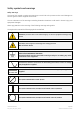
Safety symbols and warnings Safety warnings The text of this manual contains some warnings to avoid risk to the persons and to avoid damages to the UPS system and the supplied critical loads. The non-observance of the warnings reminding hazardous situations could result in human injury and equipment damages. Please pay attention to the meaning of the following warnings and symbols.
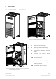
LAYOUT 2.1 LAYOUT SG Series 50 & 80 kVA SGT5000_050-080_UPS_GE_03 SGT5000 050-080 UPS GE 02 2 Q1 OFF ON OFF ON Q2 Fig. 2.1-2 SG Series general view with open doors Fig. 2.
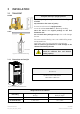
3 INSTALLATION 3.1 TRANSPORT Forklift Transport UPS only in upright position! The UPS is packaged on a pallet suitable for handling with a forklift. Pay attention to the center of gravity. The UPS must be moved in upright position. Do not tilt cabinets more than +/- 10° during handling. Move the UPS in it’s original package to the final destination site. Crane Do not stack other packages on top: This could damage the UPS.
3.2 DELIVERY When delivered, inspect the package integrity and the physical conditions of the cabinets carefully. In case of any damage sustained during transport, immediately inform the carrier and contact your local Service Center. A detailed report of the damage is necessary for any insurance claim. NOTE ! A DAMAGED UPS MUST NEVER BE INSTALLED OR CONNECTED TO UTILITY OR BATTERY! 3.3 STORAGE 3.3.
3.4 PLACE OF INSTALLATION 3.4.1 UPS location WARNING ! A qualified electrical contractor must carry out the installation and cabling of the UPS. If optional cabinets and accessories are included with the UPS, please refer to those accompanying manuals for installation and operating instructions. It is important to have a clean, dust-free environment provided with proper ventilation and airconditioning to keep the ambient temperature within the specified operating range.
Openings for input and output cable connections Battery Utility input Output Load T5 SG iew Sv UP 80_ 0-0 _05 0 0 0 US _01 top 86" 13. mm 352 2.25" 57mm 31.50" 800mm 1.18" 30mm SG Series openings are provided on the top and the bottom of the UPS for the connection of input and output cables. 50" 31. mm 800 8" 1.1 m 30m Fig. 3.4.
SGT5000_050-080_RPA disposition_GE_01US In case of parallel system, try to place the UPS modules in sequence of their numbers (marked on the packing). If the units are positioned “side by side”, the side panels must be mounted on all units. UPS 3-4-5-6-7-8 UPS 1 UPS 2 Fig. 3.4.1-6 RPA system disposition 3.4.2 Battery location Batteries require a well-ventilated room with controlled temperature to obtain reliable operation.
3.5 VENTILATION AND COOLING Fig. 3.5-1 Installation on plain floor Fig. 3.5-2 Installation on raised floor The heat produced by the UPS is transferred to the environment by its ventilation. Air inlets for UPS ventilation are located on the front of the UPS, while air outlets are on top of the cabinet. A suitable ventilation or cooling system must be installed to extract the heat from the UPS room. NOTE ! Do not put anything on the top of the cabinet.
3.6 UNPACKING The UPS and battery cabinets may be shipped packaged in carton boxes or in wooden crates (if requested). Move the cabinets as close as possible to the final location before removing from the pallet. Remove the cabinet from the pallet with care because of the heavy weight of the equipment. To unpack the cabinet follow the instructions below: 1. Wooden crate will arrive as shown. 2. Remove front and top panels. 3. Let down the ramp “A” and save wood braces “B and C” for ramp supports. 4.
7. Remove anchoring plate “E” from all four legs and unscrew supporting block screws “F”. F 8. F E 9. Divide the supporting blocks with a hammer and save blocks “G” and “H” for ramp supports. Place blocks “G” and “H” and frames “B” and “C” under ramp for support. G 10. H Make sure leveling feet are raised and carefully role UPS down ramp. G H B C NOTE ! Take care not to damage the UPS when moving by forklift.
3.7 ELECTRICAL WIRING WARNING ! UPS installation and connection must be performed by qualified service personnel only. It is the responsibility of the installation technician to ensure that all local and national electric codes are adhered to. 3.7.1 Utility input connection NOTE ! Ensure that the AC and DC external isolators are OFF and locked out to prevent their inadvertent operation. Do not apply power to the equipment prior to the commissioning by a qualified service engineer.
3.7.2 Input/output over current protection and wire sizing The cabling of the UPS system has to be sized according to the UPS power rating. Sizing of circuit breakers, fuses and cables for Input Utility, Output Load and Battery must meet the requirements of local and national electrical codes. Before connecting the UPS, verify that the Utility Voltage and Frequency, the Output Load Voltage and Frequency and Battery Data (cells number, floating voltage, autonomy) are according to the required specifications.
3.7.3 Battery over current protection and wire sizing • • • • Please read the safety precautions at the front of this guide carefully, and thoroughly review the battery manufacturers installation and maintenance manual before connecting the batteries to the UPS. If the UPS system has been purchased with an accompanying battery cabinet, that cabinet should have an integral battery circuit breaker.
NEC SECTION 210-20 (a) Table 310-16. Allowable Ampacities of Insulated Conductors Rated O Through 2000 Volts, 60°C Trough 90°C (140°F Trough 194°F) Not More than Three Current-Carrying Conductors in Raceway, Cable, or Earth (Directly Buried), Based on Ambient Temperature of 30°C (86°F).
3.8 WIRING CONNECTION WARNING! UPS installation and connection must be performed by qualified service personnel only. 3.8.1 Power connections Input/output and DC connections are provided with terminal blocks. Please refer to chart for torque specifications. Carefully read the following recommendations before proceeding: • Ensure that the AC and DC external isolators are OFF and locked to prevent their inadvertent operation. • Do not close any external isolators prior the commissioning of the equipment.
How to access the terminals for the cable connections. Top entry cables U 30-040_ SGUL_0 1US ection_0 PS conn E ! Please remove the plate "E & F" before drilling any wholes. A D C F B Bottom entry cables Fig. 3.8.1-1 Access to the input / output connections To access input, output and Battery connections proceed as follows: • Remove protection panel “A”. • Remove protection panel “B”. • Remove UPS side panel “C”.
SGT5000_050-080_UPS connection common_02US 3.8.2 Power connection with common input utility PE N L3 L2 L1 LOAD PE N L3-1 L2-1 L1-1 INPUT 1 - RECTIFIER & BYPASS OFF ON OFF ON X1 Fig. 3.8.2-1 Power connections Common Input Utility SG Series 50 & 80 kVA 4/0 AWG (95mm2) Max.
SGT5000_050-080_UPS connection separate_02US 3.8.3 Power connection dual input utility X1 PE N L3 L2 L1 X2 L3 L2-2 OFF ON L2 OFF L1-2 PE N - Bypass L3-1 INPUT 1 - RECTIFIER L2-1 L1-1 ON 2- INPUT BYPASS L3-2 LOAD L1 Fig. 3.8.3-1 Power connections Dual Input Utility SG Series 50 & 80 kVA Max.
SGT5000_050-080_UPS BR1-2-3_02 X1 X2 BR3 OFF ON OFF ON BR1 BR2 Fig. 3.8.3-2 Interconnection links BR1, BR2 and BR3 For separate Bypass and Rectifier Input configuration, the interconnection links BR1, BR2 and BR3 MUST BE REMOVED. Modifications reserved OPM_SGS_ISG_50K_80K_0US_V040.
SGT5000_050-080_UPS connection battery_02US 3.8.4 Battery connection + _ PE X3 BATTERY Fig. 3.8.4-1 Power connections battery SG Series 50 & 80kVA Max. rating Battery terminals: 4/0 AWG (95mm2) Battery + Positive pole of the Battery – Negative pole of the Battery Do not insert the Battery Fuses before the commissioning. Battery cable terminations are to the Positive and Negative Terminals as shown above. Connect wire to the Terminals using appropriate tools and appropriate torque.
3.8.5 Setup for SG Series when functioning as frequency converter When the SG Series is utilized for different output frequency compared to the input frequency, the Automatic Bypass and Manual Bypass functions are disabled, therefore the load cannot be transferred to Utility in case of overload, short circuit, or inverter failure.
3.9 RPA PARALLEL SYSTEM CONNECTION WARNING ! This operation must be performed by trained personnel before the initial start-up. ENSURE THAT THE UPS INSTALLATION IS COMPLETELY POWERED DOWN. 3.9.1 Power wiring of parallel units To guarantee good Load sharing between the units of a parallel system, we recommend that the cable length from the input distribution board (5) to the output distribution board (10) is equal for each unit (a+b = c+d = e+f = g+h = i+l = m+n = o+p = q+r). Tolerance: +/-10%.
3.9.2 Parallel control bus connection In cases of parallel operation, the communication between the units takes place through the control bus cables. Each parallel unit is equipped with an additional board “P13 – RPA Board“ where the connectors J52 (A) and J62 (B) are located. A short control cable provided with a ferrite ring core links the parallel board “P13 – RPA Board” with the parallel bus socket on which must be connected the control bus cables JA and JB on PCB “P34 – Bus Interface”.
SGT5000_100-150_RPA-IM0048_02 JB1 JP1 JP2 JB IM 0048 JP2 JP1 JP4 JP3 JA1 JP4 JP3 JA Fig. 3.9.2-2 Bus connection on terminal units Terminal units On the parallel bus PCB “P34 – Bus Interface”, of the first and last units (terminal) of the parallel system the Jumpers JP1, JP2, JP3 and JP4 MUST BE INSERTED. SGT5000_100-150_RPA-IM0048_03 JB1 JP1 JB2 JP2 JB IM 0048 JP2 JP1 JP4 JP3 JA1 JA2 JP4 JP3 JA Fig. 3.9.
3.9.3 Control bus cable location SGT5000_050-080_RPA control bus cable_01b WARNING ! This operation must be performed by trained personnel before the initial start-up. ENSURE THAT THE UPS INSTALLATION IS COMPLETELY POWERED DOWN. Access to the connection. control bus The control bus connection between parallel units must be made on the front of the electronic module fitted behind the front doors. Q1 OFF ON OFF ON Q2 JB1 A JB2 JA1 JA2 A JA JB SGT5000_100-150_RPA control bus cable_02US Fig. 3.
SGT5000_050-080_RPA control bus cable_02b_US JB1 JB JB1 JB2 JA1 JB JA JA1 JA2 JA Q1 OFF ON OFF OFF ON ON ON A OFF A Q1 Q2 Q2 JB1 JB2 JA1 UPS 1 JB2 JA2 UPS 2 JA2 Next para ll unit 3, 4, el 5, 6, 7, 8 Fig. 3.9.3-3 Control Bus cable routing and connection Control bus cables routing Place and fix the cables JA-1/2/3/4/5/6/7 and JB-1/2/3/4/5/6/7 with the appropriate clamps inside the UPS cabinets in the position shown in the drawing Fig 3.9.3-1/2/3.
CUSTOMER INTERFACE 4.
1 2 3 4 SGT5000_100-150_Customer interface J3_01 4.1.1 Serial Port J3 1 2 J3 3 4 Serial port J3 - RS-232 (sub D, female 9 pin) that allows: Total remote management of the system using new generation software JUMP (Java Universal Management Platform) for system protection and management of systems using GE UPS. JUMP system is written in JAVA and supports virtually all platforms having “JAVA runtime environment”. Fig. 4.1.
4.1.3 Programmable input free contacts Some programmable UPS functions (indicated in Section 8.1), can be activated by closing an external contact, if connected, on: X1 / 10, 21 X1 / 11, 22 or or J2 / 10, 23 J2 / 11, 24 User Input 1 (default = Not used) User Input 2 (default = Emergency GEN ON) 4.1.
4.1.7 EPO (Emergency Power Off) input contact SGT5000_100-150_Customer interface EPO_01 Be aware: The reliability of the system depends on this contact NC (Normally Closed)! 1 2 3 4 JP3 J2 1 2 3 XB An external Emergency switch (Normally Closed voltage-free contact) can be connected on terminals XB / 1 - 4 or connector J2 / 12 - 25 of the P4 - Interface Customer.
5 NOTES 5.1 NOTES FORM It is recommended to note in this section Notes, with date and short description all the operations performed on the UPS, as: maintenance, components replacement, abnormal situations, etc. Date Modifications reserved OPM_SGS_ISG_50K_80K_0US_V040.