
Installation Guide Manual


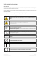
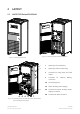
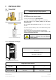
Table of contents Page
1
IMPORTANT SAFETY INSTRUCTIONS ........................................................................................................... 6
2 LAYOUT ............................................................................................................................................................ 9
2.1 LAYOUT SG Series 50 & 80 kVA.......................................................................................................................................................9
3 INSTALLATION .............................................................................................................................................. 10
3.1 TRANSPORT........................................................................................................................................................................................... 10
3.1.1 Dimensions and weight ........................................................................................................................................................................ 10
3.2 DELIVERY................................................................................................................................................................................................ 11
3.3 STORAGE................................................................................................................................................................................................ 11
3.3.1 Storage of the UPS .................................................................................................................................................................................. 11
3.3.2 Storage of battery................................................................................................................................................................................... 11
3.4 PLACE OF INSTALLATION................................................................................................................................................................ 12
3.4.1 UPS location ............................................................................................................................................................................................... 12
3.4.2 Battery location........................................................................................................................................................................................ 14
3.5 VENTILATION AND COOLING ........................................................................................................................................................ 15
3.6 UNPACKING.......................................................................................................................................................................................... 16
3.7 ELECTRICAL WIRING ......................................................................................................................................................................... 18
3.7.1 Utility input connection......................................................................................................................................................................... 18
3.7.2 Input/output over current protection and wire sizing............................................................................................................. 19
3.7.3 Battery over current protection and wire sizing........................................................................................................................ 20
3.8 WIRING CONNECTION...................................................................................................................................................................... 22
3.8.1 Power connections.................................................................................................................................................................................. 22
3.8.2 Power connection with common input utility............................................................................................................................. 24
3.8.3 Power connection dual input utility ................................................................................................................................................ 25
3.8.4 Battery connection ................................................................................................................................................................................. 27
3.8.5 Setup for SG Series when functioning as frequency converter.......................................................................................... 28
3.9 RPA PARALLEL SYSTEM CONNECTION...................................................................................................................................... 29
3.9.1 Power wiring of parallel units............................................................................................................................................................. 29
3.9.2 Parallel control bus connection......................................................................................................................................................... 30
3.9.3 Control bus cable location................................................................................................................................................................... 32
4 CUSTOMER INTERFACE................................................................................................................................34
4.1 CUSTOMER INTERFACE.................................................................................................................................................................... 34
4.1.1 Serial Port J3 .............................................................................................................................................................................................. 35
4.1.2 Output free potential contacts .......................................................................................................................................................... 35
4.1.3 Programmable input free contacts ................................................................................................................................................. 36
4.1.4 Gen Set Signalling (GEN ON)................................................................................................................................................................ 36
4.1.5 AUX external Maintenance Bypass................................................................................................................................................. 36
4.1.6 Auxiliary Power Supply (APS) 24 VDC.............................................................................................................................................. 36
4.1.7 EPO (Emergency Power Off) input contact................................................................................................................................... 37
5 NOTES............................................................................................................................................................. 38
5.1 NOTES FORM........................................................................................................................................................................................ 38
Modifications reserved Page 5/38
OPM_SGS_ISG_50K_80K_0US_V040.doc Installation Guide SG Series 50 & 80 kVA