
Instruction Manual

GE
Data Sheet
SHHD003A0A Hammerhead
Series; DC-DC Converter Power Modules
18-75Vdc Input; 5.0Vdc, 3A, 15W Output
June 26, 2013 ©2012 General Electric Company. All rights reserved. Page 10
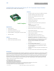
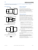
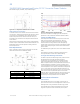
Note: All dimensions in mm [in].
Figure 19. Pick and Place Location.
Z Plane Height
The ‘Z’ plane height of the pick and place location is 7.50mm
nominal with an RSS tolerance of +/-0.25 mm.
Nozzle Recommendations
The module weight has been kept to a minimum by using open
frame construction. Even so, they have a relatively large mass
when compared with conventional SMT components.
Variables such as nozzle size, tip style, vacuum pressure and
placement speed should be considered to optimize this
process.
The minimum recommended nozzle diameter for reliable
operation is 5mm. The maximum nozzle outer diameter, which
will safely fit within the allowable component spacing, is
6.5mm.
Oblong or oval nozzles up to 11 x 6 mm may also be used
within the space available.
For further information please contact your local GE Technical
Sales Representative.
Reflow Soldering Information
These power modules are large mass, low thermal
resistance devices and typically heat up slower than other
SMT components. It is recommended that the customer
review data sheets in order to customize the solder reflow
profile for each application board assembly.
The following instructions must be observed when SMT
soldering these units. Failure to observe these instructions
may result in the failure of or cause damage to the modules,
and can adversely affect long-term reliability.
There are several types of SMT reflow technologies currently
used in the industry. These surface mount power modules
can be reliably soldered using natural forced convection, IR
(radiant infrared), or a combination of convection/IR. The
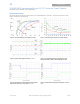
recommended linear reflow profile using Sn/Pb solder is
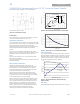
shown in Figure 20 and 21. For reliable soldering the solder
reflow profile should be established by accurately
measuring the modules CP connector temperatures.
REFLOW TEMP (C)
REFLOW TIME (S)
Figure 20. Recommended Reflow Profile for Sn/Pb solder.
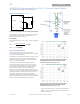
Figure 21. Time Limit, T
lim
, Curve Above 205
o
C Reflow .
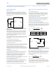
Lead Free Soldering
The –Z version SMT modules of the SHHD series are lead-free
(Pb-free) and RoHS compliant and are compatible in a Pb-free
soldering process. Failure to observe the instructions below
may result in the failure of or cause damage to the modules
and can adversely affect long-term reliability.
Figure 22. Recommended linear reflow profile using
Sn/Ag/Cu solder.
MSL Rating
The SHHD001A3B series SMT modules have a MSL rating of 2a.
0
50
10 0
15 0
200
250
300
P reheat zone
max 4
o
Cs
-1
Soak zone
30-240s
Heat zone
max 4
o
Cs
-1
Peak Temp 235
o
C
Cooling
zo ne
1- 4
o
Cs
-1
T
lim
above
205
o
C
Per J-STD-020 Rev. C
0
50
100
150
200
250
300
Reflow Time (Seconds)
Reflow Temp (°C)
Heating Zone
1°C/Second
Peak Temp 260°C
* Min. Time Above 235°C
15 Seconds
*Time Above 217°C
60 Seconds
Cooling
Zone
MAX TEMP SOLDER (C)
TIME LIMIT (S)
200
205
210
215
220
225
230
235
240
0 10 203040 5060