
Instruction Manual

GE
Data Sheet
SHHD003A0A Hammerhead
Series; DC-DC Converter Power Modules
18-75Vdc Input; 5.0Vdc, 3A, 15W Output
June 26, 2013 ©2012 General Electric Company. All rights reserved. Page 4
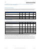
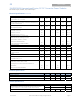
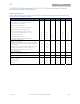
Feature Specifications
Unless otherwise indicated, specifications apply over all operating input voltage, resistive load, and temperature conditions. See
Feature Descriptions for additional information.
Parameter Device Symbol Min Typ Max Unit
Remote On/Off Signal Interface
(V
IN
=V
IN, min
to V
IN, max
; open collector or equivalent,
Signal referenced to V
IN-
terminal)
Negative Logic: device code suffix “1”
Logic Low = module On, Logic High = module Off
Positive Logic: No device code suffix required
Logic Low = module Off, Logic High = module On
Logic Low - Remote On/Off Current (V
on/off
= -0.7V
dc
) All I
on/off
0.15 mA
Logic Low - On/Off Voltage All V
on/off
-0.7
0.8 V
dc
Logic High Voltage (I
on/off
= 0A
dc
) All V
on/off
2.0
18 V
dc
Logic High maximum allowable leakage current All I
on/off
25 μA
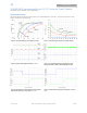
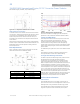
Turn-On Delay and Rise Times
(I
O
=80% of I
O, max
, T
A
=25°C)
Case 1: Input power is applied for at least 1second, and then the
On/Off input is set from OFF to ON (T
delay
= on/off pin transition until
V
O
= 10% of V
O, set
)
All
T
delay
Case1
10 20 ms
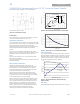
Case 2: On/Off input is set to Module ON, and then input power is
applied (T
delay
= V
IN
reaches V
IN, min
until V
O
= 10% of V
O,set
)
All
T
delay
Case2
10 20 ms
Output voltage Rise time (time for V
o
to rise from 10%
of V
o,set
to 90% of V
o, set
)
All T
rise
10 20 ms
Output Voltage Overshoot
3 % V
O, set
(I
O
=80% of I
O, max
, V
IN
= 24 to 48V
dc
, T
A
=25°C)
Output Overvoltage Protection
All V
O, limit
5.9 7.2 V
dc
Input Undervoltage Lockout
Turn-on Threshold All V
uv/on
17 18 V
dc
Turn-off Threshold All V
uv/off
14 15
V
dc
Hysterisis All V
hyst
2.0
V
dc