
Instruction Manual

GE
Data Sheet
SHHD003A0A Hammerhead
Series; DC-DC Converter Power Modules
18-75Vdc Input; 5.0Vdc, 3A, 15W Output
June 26, 2013 ©2012 General Electric Company. All rights reserved. Page 6
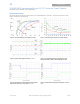
Test Configurations
TO OSCILLOSCOPE
CURRENT PROBE
L
TEST
12μH
BATTERY
C
S
220μF
E.S.R.<0.1
@ 20°C 100kHz
33μF
Vin+
Vin-
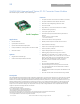
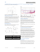
NOTE: Measure input reflected ripple current with a simulated
source inductance (L
TEST
) of 12μH. Capacitor C
S
offsets
possible battery impedance. Measure current as shown
above.
Figure 7. Input Reflected Ripple Current Test Setup.
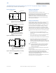
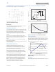
NOTE: All voltage measurements to be taken at the module
terminals, as shown above. If sockets are used then
Kelvin connections are required at the module terminals
to avoid measurement errors due to socket contact
resistance.
V
O
(+)
V
O
(
–
)
1uF
.
R ESI STI V E
LO A D
SC O P E
COPPER STRIP
GROUND PLANE
10uF
Figure 8. Output Ripple and Noise Test Setup.
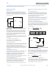
Vout+
Vout-
Vin+
Vin-
R
LOAD
R
contact
R
distribution
R
contact
R
distribution
R
contact
R
contact
R
distribution
R
distribution
V
IN
V
O
NOTE: All voltage measurements to be taken at the module
terminals, as shown above. If sockets are used then
Kelvin connections are required at the module terminals
to avoid measurement errors due to socket contact
resistance.
Figure 9. Output Voltage and Efficiency Test Setup.
=
V
O
. I
O
V
IN
. I
IN
x
100
%
Efficiency
Design Considerations
Input Source Impedance
The power module should be connected to a low
ac-impedance source. Highly inductive source impedance can
affect the stability of the power module. For the test
configuration in Figure 7, a 33μF electrolytic capacitor
(ESR<0.7 at 100kHz), mounted close to the power module
helps ensure the stability of the unit. Consult the factory for
further application guidelines.
Safety Considerations
For safety-agency approval of the system in which the power
module is used, the power module must be installed in
compliance with the spacing and separation requirements of
the end-use safety agency standard, i.e., UL 60950-1-3, CSA
C22.2 No. 60950-00, and VDE 0805 (IEC60950, 3
rd
Edition).
If the input source is non-SELV (ELV or a hazardous voltage
greater than 60 Vdc and less than or equal to 75Vdc), for the
module’s output to be considered as meeting the requirements
for safety extra-low voltage (SELV), all of the following must be
true:
The input source is to be provided with reinforced
insulation from any other hazardous voltages, including
the ac mains.
One V
IN
pin and one V
OUT
pin are to be grounded, or both
the input and output pins are to be kept floating.
The input pins of the module are not operator accessible.
Another SELV reliability test is conducted on the whole
system (combination of supply source and subject
module), as required by the safety agencies, to verify that
under a single fault, hazardous voltages do not appear at
the module’s output.
Note: Do not ground either of the input pins of the module
without grounding one of the output pins. This may
allow a non-SELV voltage to appear between the
output pins and ground.
The power module has extra-low voltage (ELV) outputs when
all inputs are ELV.
For input voltages exceeding –60 Vdc but less than or equal to
–75 Vdc, these converters have been evaluated to the
applicable requirements of BASIC INSULATION between
secondary DC MAINS DISTRIBUTION input (classified as TNV-2
in Europe) and unearthed SELV outputs.
The input to these units is to be provided with a maximum 3A
time-delay fuse in the ungrounded lead.